
Manufacturing Process Planning of Concrete Mixer Driving System
on 3D Concrete Printing Machine for Civil Buildings
Mohamad Fauzi, Tiara Gapuraning Rahayu and Heri Setiawan
Bandung Polytechnic for Manufacturing, Bandung, Indonesia
Keywords: 3D Concrete Printing Machine, Concrete Mixer, Manufacturing Planning.
Abstract: 3D Concrete Printing (3DCP) is a tool that functions to make a building construction automatically. The way
3DP works is to print material layer by layer to form a desired object. A 3D Concrete Printing (3DCP) consists
of Mixer, Nozzle, X-axis Pillar, Y-axis Pillar, and Z-axis Pillar. A concrete mixer on the 3DCP machine is a
tool that functions to mix cement, aggregate, and water homogeneously to form concrete to be distributed and
printed. Generally, the concrete mixer has 4 part-functions, namely the drive function, the container function,
the stirring function and the frame function. The planning of the construction of a concrete mixer driving
system is expected to produce the design and manufacturing stages of the concrete mixer driving system that
can rotate the container system to mix geopolymer cement, aggregate, and water so as to form geopolymer
cement concrete with good homogenization that can meets the needs of geopolymer cement concrete to be
printed.
1 INTRODUCTION
Additive Manufacturing (AM) is one of the methods
where in the process the addition of material is carried
out to make the desired shape. AM is a formal term
for what is called rapid prototyping (RP) and what is
popularly called 3D Printing (3DP) (Gibson, 2015).
The way 3DP works is to print the material layer by
layer until it forms a desired object (Erfiansyah,
2020).
3D Concrete Printing (3DCP), is an innovative
construction method that has recently been
introduced to the construction industry and has
proven to be profitable in terms of optimizing
construction time, cost, design flexibility, and
reducing errors and being environmentally friendly
(Malaeb, 2019). Politeknik Manufaktur Bandung,
which has a vision of becoming a leading institution
in the education, development, and application of
manufacturing technology, plans to design and
manufacture a 3D concrete printing machine for civil
buildings.
The main material in making buildings using 3D
printing techniques is geopolymer cement mixed with
water and aggregate, which will be printed layer by
layer until after setting and hardening will form a
geopolymer cement concrete according to the
working area of 3D Concrete Printing.
Geopolymer cement is obtained from the mixing
process of fly ash and activators in the form of NaOH
(flakes) and Na2SiO3 (granules). Geopolymer
cement must be stirred with water and aggregate to
produce geopolymer cement concrete (Yasin, n.d.).
The process of stirring or mixing geopolymer cement
and water and aggregate cannot be done manually
because manual stirring is not able to meet the needs
of geopolymer cement concrete to be printed. From
these problems, a tool is needed that can stir
geopolymer cement, water and aggregate until it is
mixed into geopolymer cement concrete. The tool
used to agitate concrete is commonly called a
concrete mixer (Wankhede, 2015). In this case, the
author's focus is to make a plan for the manufacture
of a concrete mixer driving system on a 3D concrete
printing machine of civil buildings.
2 METHOD
In the planning process of making a concrete mixer
driving system, there is a design process that adopts
VDI 2221 design method. The VDI 2221 method is a
method with a systematic approach to solving
Fauzi, M., Rahayu, T. and Setiawan, H.
Manufacturing Process Planning of Concrete Mixer Driving System on 3D Concrete Printing Machine for Civil Buildings.
DOI: 10.5220/0011891400003575
In Proceedings of the 5th International Conference on Applied Science and Technology on Engineering Science (iCAST-ES 2022), pages 813-820
ISBN: 978-989-758-619-4; ISSN: 2975-8246
Copyright © 2023 by SCITEPRESS – Science and Technology Publications, Lda. Under CC license (CC BY-NC-ND 4.0)
813
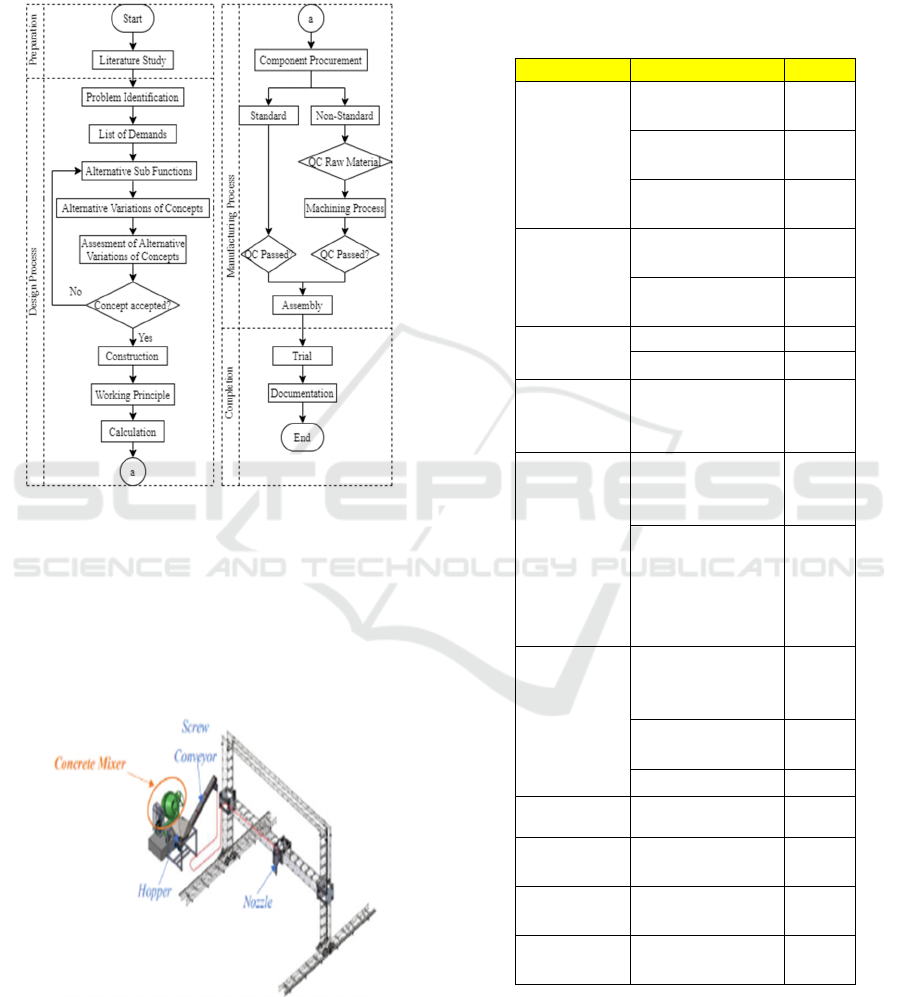
problems and optimizing the use of materials and
technology. After the design process is completed,
manufacturing process must be conducted according
to completed design. The following is a complete
flowchart of the manufacturing process planning.
Diagram 1: Flow Process.
3 RESULT AND DISCUSSION
3.1 Design Process
3.1.1 Problem Identification
Figure 1: Concrete Mixer on 3DCP.
In 3D Concrete Printing technology, a tool is needed
that cn do material stirring (it can also be called a
concrete mixer) for then the material results in the
form of geopolymer cement concrete is ready to be
printed. There are several functions of parts of a
concrete mixer. The author's focus is on the
geopolymer cement stirring drive system.
3.1.2 List of Demands
Table 1: List of Demands.
Parameter Specification Priority
Manufacture Standard
components
*
Existing
components
**
Borrowable
components
*
Assembly Easy assembly
system
**
Can be
disassembled
*
Construction Sturdy *
Simple **
Kinematics Mixer tank rotates
at a speed of 40-50
rpm
*
Operation Easy and
ergonomic when
operated
**
Can be used for
stirring geopolymer
cement to form
geopolymer cement
concrete
*
Maintenance Ergonomic during
installation and
maintenance
**
Easy maintenance
and repair
**
Easy to clean **
Safety Safe operation *
Cost Minimum
production cost
**
Resistance Has a long lifetime **
Aesthetic Appealing visual **
iCAST-ES 2022 - International Conference on Applied Science and Technology on Engineering Science
814
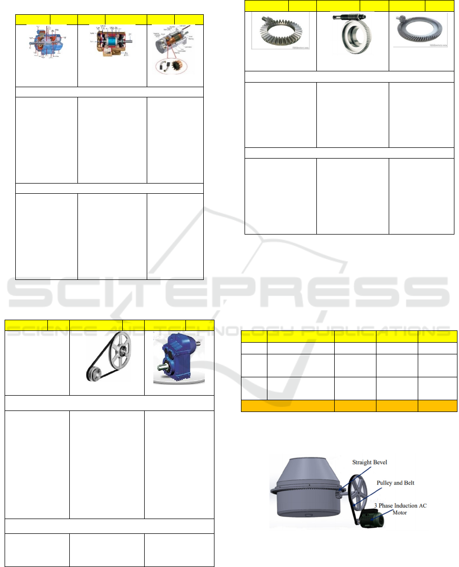
3.1.3 Alternative Sub Functions
Table 2: Alternative Sub Functions: Drive Source.
Alt 1 A1 Alt 2 A2 Alt 3 A3
3 Phase
Induction AC
Moto
r
1 Phase Induction
AC Motor
Motor DC
Excess
• The use of
electrical
power is
more
efficient.
• Suitable for
use in
industrial
machinery.
• Construction is
simpler.
• Relatively
cheaper.
• Speed and
torque are
easier to
manage.
Deficiency
• Relatively
more
expensive
than 1 phase
induction
motors.
• It is more
suitable for use
in low-power
and medium-
load
applications.
• The relative
price is the
most
expensive.
• Not suitable
for large-
power and
high-speed
applications.
Table 3: Alternative Sub Functions: First Transmission
Element.
Alt 1 B1 Alt 2 B2 Alt 3 B3
Without
transmission
elements
Pulleys and Belts
Gearbox
Excess
• Fewer and
simpler
components
• It can dampen
shock loads,
noise and
vibration.
• Easy design and
flexible, do not
require high
tolerances.
• Relatively
cheaper.
• The
transmission
efficiency is
higher because
no slip occurs.
• Mechanically
stronger.
Deficiency
• Put
operation at
risk.
• Not as
compact as to
gears.
• More
complex
design.
Table 4: Alternative Sub Functions: Second Transmission
Element.
Alt 1 C1 Alt 2 C2 Alt 3 C3
Straight Bevel
Gear
Worm Gear
Spiral Bevel
Gea
r
Excess
• High
transmission
efficiency.
• Construction
is simpler.
• Large shock
load capacity.
• It's quieter.
• High
transmission
efficiency.
• The load
capacity is
lar
g
e
r
Deficienc
y
• Produces
greater
vibration and
sound
compared to
spiral bevel
gear.
• Lower
transmission
efficiency.
• At risk during
installation
and use of the
en
g
ine.
• Complex
construction
3.1.4 Alternative Variations of Concepts
Alternative of concept variations will be assessed and
the one with the highest value will be selected for
further detailed designing.
Table 5: Morphology Box.
The following are alternative results of variations in
concepts:
Figure 2: 1
st
Alternative of Concept Variations.
No. Component Var 1 Var 2 Var 3
1. Drive motor A1 A2 A3
2. Transmission
element 1
B1 B2 B3
3. Transmission
element 2
C1 C2 C3
Concept Variations ACV1 ACV2 ACV3
Manufacturing Process Planning of Concrete Mixer Driving System on 3D Concrete Printing Machine for Civil Buildings
815
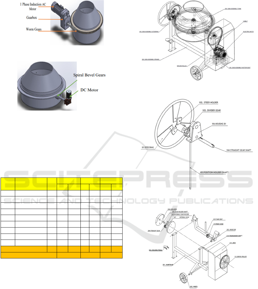
Figure 3: 2
nd
Alternative of Concept Variations.
Figure 4: 3
rd
Alternative of Concept Variations.
All modeling variations are assessed according to:
Nominal 5: Excellent, very achieved, and very easy.
Nominal 4: Good, achieved, and easy.
Nominal 3: Good enough, quite achieved, and quite easy.
Nominal 2: Not good, less achieved, and less easy
Nominal 1: Not good, not achieved, and not easy.
Table 6: Assessment of Alternative Concept Variations.
No. Parameter W
ACV 1 ACV 2 ACV 3
P ST P ST P ST
1. Manufacture 4 3 12 3 12 3 12
2. Assembl
y
3 3 9 2 6 3 9
3. Construction 5 3 15 3 15 2 10
4. O
p
eration 5 4 20 4 20 4 20
5. Maintenance 3 4 12 3 9 3 9
6. Safet
y
5 4 20 3 15 2 10
7. Cost 3 4 12 3 9 3 9
8. Aesthetic 2 3 6 4 8 3 6
9. Resistance 4 3 12 4 16 2 8
Total Value 34 31 118 29 110 25
9
3
Percentage 86.7% 80.8% 68.4%
3.1.5 Construction
This stage contains documents that include machine
drawings, machine drawing details, a list of
components, and other documents connected into a
single entity. Here's the overall construction drawing
of the selected 1
st
Alternative of Concept Variations
(ACV1):
Figure 5: Assembly Construction of Concrete Mixer.
Figure 6: Construction of Sub-assy Steering.
Figure 7: Construction of Sub-assy Frame.
iCAST-ES 2022 - International Conference on Applied Science and Technology on Engineering Science
816

Figure 8: Construction of Sub-assy Tank.
Figure 9: Construction of Sub-assy Motor Seat.
3.1.6 Working Principle
Figure 10: Working Principle Illustration.
The working principle of the concrete mixer driving
system is that when the motor as the driving source is
electrified, the motor shaft will rotate, the power and
rotation of the motor shaft are then transmitted to the
transmission system in the form of a pulley and belt,
then passed to the transmission shaft. The rotation of
the transmission shaft is passed to the pinion gear.
The pinion gear rotates its pair, namely the crown
gear that circles the mixer tank so that the mixer tank
can rotate on its axis according to the rotation ratio to
stir the geopolymer cement, water, and aggregate to
form geopolymer cement concrete.
3.1.7 Calculation
Three Phase Induction AC Motor. The motor used
is in accordance with the availability of components
in Polman, with specifications:
• Motor output power = 3.7 kW
• Motor rev = 2890 rpm
• Loading torque = 13,21 Nm
Pulleys and Belts
a. Specifications of pulleys and belts
On the available concrete mixer, there are large pulley
(driven pulley).
Known:
• Large pulley pitch diameters:𝐷
450 𝑚𝑚
• Belt type required = V-Belt type A
• Number of belts required = 2 pieces
Asked:
• Small pulley pitch diameter?
• Shaft distance?
• Belt length?
Answer:
• Small pulley pitch diameter (𝑑
)
→
→𝑑
68 𝑚𝑚 (1)
• Shafts’ Distance Range (C)
The distance between two shafts must meet the
following conditions:
𝐶0,7 𝑑
𝐷
and 𝐶2𝑑
𝐷
(2)
𝐶0,7 68 450 and 𝐶268 450
𝐶362,6 and 𝐶1036
365 mm of shafts’ distance is selected.
• Belt length (L)
𝐿
2. 𝐶
𝑑
𝐷
.
𝐷
𝑑
(3)
𝐿
2.365
𝜋
2
68 450
1
4.365
450 68
𝐿
1643,2 𝑚𝑚
The belt length of the calculation result is adjusted
to the standard on ISO 4184, the belt length is
1655
𝐿
𝐿
mm, which is belt number A46.
• Distance between shafts (C)
The distance between shafts according to the standard
belt length can be calculated by the formula:
𝐶
(4)
𝐶
2.1655 𝜋
450 68
2.1655 𝜋450 68
8
450 68
8
𝐶371,81 𝑚𝑚
Manufacturing Process Planning of Concrete Mixer Driving System on 3D Concrete Printing Machine for Civil Buildings
817

b. Transmission efficiency
Based on calculations, it is known:
• Belt linear speed (V) =10,28
𝑚
𝑠
⁄
• Belt tight side tension 𝑇
=347,28 𝑁
• Belt saggy side tension 𝑇
=95,79 𝑁
Asked:
• Transmission efficiency?
Answer:
Determining torque
𝑇
𝑇
𝑇
𝑟 (5)
𝑇
347,28 95,79
0,034
𝑇8,56 𝑁. 𝑚
Determining the transmitted power
𝑃
𝑇𝜔 (6)
𝑃
𝑇
2𝜋𝑛
60
𝑃
8,56
2𝜋2890
60
𝑃
3009 𝑤𝑎𝑡𝑡 3 𝑘𝑊
Determining transmission efficiency
𝜂
100% (7)
𝜂
3
3,7
100% 81 %
Straight Bevel Gears. On the available concrete
mixer, there are straight bevel gears in the form of
pinion bevel gear and crown bevel gear.
Known:
• The rotation of the tank is desirable (the rotation of
the crown gear): n
45 50 rpm, taken 48 rpm.
• Number of pinion gear: Z
12
• Number of crown gear:Z
108
Asked:
• Pinion bevel rotation to make the crown gear
rotates 48 rpm?
Answer:
→
→𝑛
436 𝑟𝑝𝑚 (8)
Power to Rotates Mixer Tank. The power required
to rotate the tank is the power needed by the pinion
bevel gear to rotate the crown bevel gear.
Figure 11: Illustration of pinion gear rotating crown gear.
Known:
• Power received by pinion gear from the pulley and
belt transmission system = 3009 watts
• Pinion gear rotational speed (n1) = 436 rpm
• Crown bevel gear rotational speed (n2) = 48 rpm
• Mass of mixer tank= 98.58 kg
• Mass of crown gear = 32,40 kg
• Maximum capacity of tank load = 300 kg
• Diameter pitch pinion gear:d
100,9 mm
• Diameter pitch crown gear:d
908,3 mm
Asked:
• Power, force and torque on the pinion gear?
• The force, torque and power required to rotate the
crown gear?
Answer:
• Power, force and torque on the pinion gear
Figure 12: Illustration of the force that occurs in the pinion
gear.
The power received by the pinion gear of the pulley
and belt transmission system is:
𝑃3009 𝑤𝑎𝑡𝑡
Tangential force that occurs in the pinion gear that
can be passed to the crown gear:
P T. ω (9)
𝑃𝐹
. 𝑟.
2𝜋. 𝑛
60
𝐹
𝑃. 60
𝑟 .2𝜋. 𝑛
𝐹
3009. 60
0,05 . 2𝜋. 436
𝐹
1318 𝑁
The torque required to rotate the pinion gear is:
𝑇𝐹
. 𝑟 (10)
𝑇1318 . 0,05
𝑇65,94 𝑁𝑚
• The force, torque and power required to rotate the
crown gear
iCAST-ES 2022 - International Conference on Applied Science and Technology on Engineering Science
818

Figure 13: Illustration of the force that occurs in the crown
gear.
Looking for tangential force, which is the force that
acts on the crown gear to move in a circle in the
tangential direction of a curved trajectory.
F
m. a
(11)
F
m
m
m
α.r
F
98,58 32,40 3005,02 . 0,45
F
973,58 N
After the tangential force is obtained, the torque,
which is the force required for the crown gear to rotate
on its axis at a distance r, can be calculated by the
formula:
T F
.r (12)
T 973,58 . 0,45
T 438,11 Nm
The power required to rotate the crown gear can be
calculated by:
P T. ω (13)
P 438,11 .
2π.48
60
P 2199 watt 2,2 kW
• Conclusion:
o Tangential force of crown gear < pinion gear
o The power required by crown gear < the power that
the pinion gear receives to be passed on.
o If the calculation of torque with the rotation ratio is
carried out, the torque on the pinion gear and on the
crown gear < the loading torque of the motor which
is 13.21 Nm.
o It can be concluded that the pinion gear can rotate
the crown gear, which means that the tank can
rotate to stir the material that makes up the
geopolymer cement concrete at the maximum
capacity of the tank, which is 300 kg.
Composer Material of Geopolymer Cement
Concrete. Based on the specifications of pulleys and
belts, straight bevel gears, as well as the power ability
of the motor to rotate the tank, the composition of the
material that can be stirred by the concrete mixer is as
follows:
Table 7: The composition of the stirred material.
No. Identification
1.
T
ank capacit
y
• Tank capacity accommodates load at motor
power 3.7 kW = 300 kg
• It is known that the density of geopolymer
cement is 2400 kg/mm
3
, so the volume of
geopolymer cement that can be accommodated is
=
0,125 𝑚
125 𝑙𝑖𝑡𝑒𝑟
2. The number of each constituent component of
geopolymer cement concrete
With a total capacity of 300 kg, each constituent
component of geopolymer cement concrete is:
1. Geopolymer cement (30%) = 85 kg
2. Water (0,159xgeopolymer cement) = 13,5 kg
3. Coarse aggregate (3/5 x 70%) = 118.8 kg
4. Fine aggregate (2/5 x 70%) = 79.2 kg
3.2 Manufacturing Process
3.2.1 Component Procurement
Table 8: Component of Concrete Mixer Drive System.
No. Component Name Qty
Component Availabilit
y
Yes
No
Standar
d
Non
Electrical Components
1. 3
p
hase AC moto
r
1
√
2. Switch Button 1
√
3. Magnetic contact 1
√
4. Thermal overload rela
y
1
√
5. Pilot lam
p
o
ff
1
√
6. Pilot lam
p
on 1
√
7. NYA cable re
d
1
√
8. NYA cable blac
k
1
√
9. NYA blue cable 1
√
Mechanical Com
p
onents
1. Motor seat 1
√
2
. Driver
p
ulle
y
1
√
3.
B
elt 2
√
4
. Driven pulley 1
√
5. Transmission shaft 1
√
6. T
yp
e A 8×7
p
arallel
p
e
g
2
√
7. Type A 10×8
p
aralle
l
p
egs
1 √
8. Bolt M8 1
√
9. Washe
r
1
√
10. Bearin
g
6205-ZR 1
√
11. Housing bearing 1
√
12. Pinion bevel gea
r
1
√
13. Crown bevel
g
ea
r
1
√
Manufacturing Process Planning of Concrete Mixer Driving System on 3D Concrete Printing Machine for Civil Buildings
819
3.2.2 Machining Process Planning
The stages of the machining process are the sequence
of processes to make raw material into the desired
component. The following are Working process
stages of non-standard components that need to be
made, namely motor seat component.
Table 9: Working process stages of non-standard
components.
No. Component Qty Work Process
1. Motor seat part 1 2 CG-HG-DR
2. Motor seat part 2 2 CG-DR-MI-EW-HG
3. Motor seat
p
art 3 2 CG-DR
CG= Cutting grinding, DR=Drill, HG=Hand
grinding, MI=Milling, EW=Electric welding
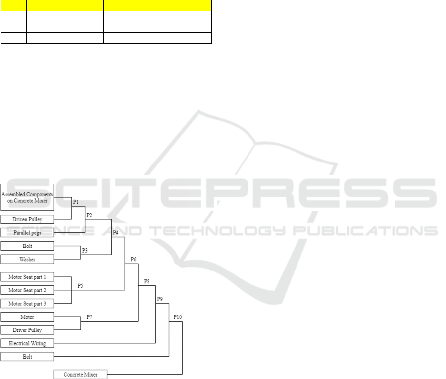
3.2.3 Assembly Planning
Assembly is a process of compiling and unifying
several component parts into a tool or machine that
has a certain function. These assembly activities
include drafting, placing, fastening, and measuring.
The following are the assembly stages of the drive
system on the concrete mixer:
Diagram 2: Component Assembly Diagram of Concrete
Mixer Driving System.
3.2.4 Trial
The trial stage is carried out to ensure that the
concrete mixer can be used according to its function.
This aims to determine the tank's ability to stir
geopolymer material, so it is expected that after the
trial stage, what can be obtained is the data on the
ideal capacity of geopolymer material that can be
stirred by concrete mixer and the time required to
achieve homogenization of materials.
4 CONCLUSIONS
The working principle of the concrete mixer driving
system is that when the motor as the driving source is
electrified, the motor shaft will rotate, the power and
rotation of the motor shaft are then transmitted to the
transmission system in the form of a pulley and belt,
then passed to the transmission shaft. The rotation of
the transmission shaft is passed to the pinion gear.
The pinion gear rotates its pair, namely the crown
gear that circles the mixer tank so that the mixer tank
can rotate on its axis according to the rotation ratio to
stir the geopolymer cement, water, and aggregate to
form geopolymer cement concrete.
In planning the manufacture of this concrete mixer,
the process begins with the design method of VDI
2221, then continues with the planning process, then
continues with the process of procurement of
components. After that, the process of machining,
assembly, trial and document collection should be
carried out.
REFERENCES
Gibson, Ian. Stucker, Brent. Rosen, David. (2015). Additive
Manufacturing Technologies. New York: Springer
Erfiansyah. Erfin. (2020). DESIGN OF CARTESIAN
TYPE 3D PRINTING MACHINE CONSTRUCTION
BASED ON FUSED DEPOSITION MODELING.
Bandung: Politeknik Manufaktur Negeri Bandung.
Malaeb, Zevia. AlSakka, Fatima. Hamzeh, Farook. (2019).
3D Printing. Lebanon: Elsevier Inc.
Yasin. Abdul Karim. (2019) ASH-BASED
GEOPOLYMER CONCRETE ENGINEERING.
Surabaya: Ten November Institute of Technology.
Wankhede. Amruta K, Sahu. A. R. (2015). Design,
Modification and Analysis of Concrete Mixer Machine.
G. Pahl, W. Beitz, J. Feldhusen, dan K. H. Grote. (2007).
Engineering design: A systematic approach.
Sularso and K. Suga. (2004). Basic Planning and Selection
of Machine Elements. Jakarta: PT. Pradnya Paramita.
Jelaska. Damir. (2012). Gears and Gear Drives. Croatia: A
John Wiley & Sons, Ltd., Publication.
Ichniarsyah, Nur Annissa. A, Azhar. (2019). MOTOR
DRIVE. Jakarta: Agricultural Education Center.
Waloeyo, Gamawan A. (2009). PPC Basic Cost. Bandung:
Politeknik Manufaktur Negeri Bandung.
iCAST-ES 2022 - International Conference on Applied Science and Technology on Engineering Science
820
