
The Manufacturing Process of Geopolymer Mortar Nozzle
Construction on Civil Building 3D Printing Machine
Antonius Adi Soetopo
1
, Heri Setiawan
2
and Alvian Andriansyah
1
1
Polman Bandung, Indonesia
2
Politeknik Manufaktur Bandung, Indonesia
Keywords: Nozzle, Geopolymer Mortar, Manufacturing Process.
Abstract: The geopolymer mortar nozzle is one of the components contained in the 3D printing machine of civil
buildings that serves to remove the geopolymer mortar into a certain shape. A civil building 3D printing
machine requires a tool or device designed to control the shape or characteristics of the material flow specially
to regulate the number of geopolymers when exiting a hopper.
The nozzle will store the geopolymer mortar on the hopper, then with the rotation of the stepper motor and
extruder, the geopolymer mortar will come out into a certain shape through the nozzle head. The construction
of the geopolymer mortar nozzle on the 3D printing machine of civil buildings is carried out by cutting plates
using hand grinding and cutting grinding, turning, bending, and welding for the assembly process. After this
geopolymer mortar nozzle is completed and realized at the Manufacturing Engineering Department of the
Bandung Manufacturing Polytechnic, this geopolymer mortar nozzle is expected to be used for the
manufacture of civil buildings and function properly and benefit the polman academic community, the
community, and the State of Indonesia.
1 INTRODUCTION
Civil building 3D printing machine is a machine that
processes geopolymer mortar under computer control
to create three-dimensional objects, with materials
added together (geopolymer concrete, sand, and
water combined). Objects can be either shapes or
geometries and are typically generated using digital
model data from 3D models derived from Additive
Manufacturing Files (AMF). 3D printing builds a
three-dimensional object from a computer-aided
CAD model or AMF file, by adding layers of material
layer by layer in a row.
This civil building 3D printing machine requires a
device or devices designed to control the shape or
characteristics of the material flow (specially to
regulate the number of geopolymers) when exiting (or
entering) a hopper called a nozzle. Oleh therefore, in
this case the author focuses on "Proses Manufacture
of Geopolymer Mortar Nozzle Construction On 3D
Printing Machines of Civil Buildings
2 PURPOSE
The purpose of making this tool is as follows:
1. Knowing the construction of the geopolymer
mortar nozzle on the 3D printing machine of civil
buildings.
2. Knowing the work of the geopolymer mortar
nozzle on the 3D printing machine of civil
buildings.
3. Knowing the manufacturing process of
geopolymer mortar nozzle construction on a civil
building 3D printing machine.
4. Knowing the estimated time required to make the
construction of the geopolymer mortar nozzle on
the civil building 3D printing machine.
5. Knowing the estimated cost needed to make the
construction of a geopolymer mortar nozzle on a
civil building 3D printing machine.
Soetopo, A., Setiawan, H. and Andriansyah, A.
The Manufacturing Process of Geopolymer Mortar Nozzle Construction on Civil Building 3D Printing Machine.
DOI: 10.5220/0011893400003575
In Proceedings of the 5th International Conference on Applied Science and Technology on Engineering Science (iCAST-ES 2022), pages 843-849
ISBN: 978-989-758-619-4; ISSN: 2975-8246
Copyright © 2023 by SCITEPRESS – Science and Technology Publications, Lda. Under CC license (CC BY-NC-ND 4.0)
843
3 MANUFACTURING PROCESS
3.1 Manufacturing Process Flow
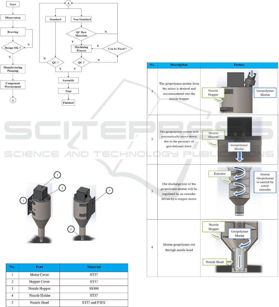
The process of making the construction of a
geopolymer mortar nozzle consists of several stages,
these stages can be described in general on the
following flow chart:
Diagram 1: Flow Chart of The Construction Process of
Geopolymer Mortar Nozzle Construction.
3.2 Construction Nozzle Mortar
Geopolymers
Below is a picture of the construction of the
geopolymer mortar nozzle:
Figure 1: Construction of the Geopolymer Mortar Nozzle.
Figure 2: List of Parts Names and Materials for
Construction of Geopolymer Mortar Nozzles.
Material is the raw material for the manufacturing
process both directly from natural and artificial which
will be processed into a product. The main materials
used in the manufacturing process of geopolymer
mortar nozzle construction in civil crane 3D printing
machines are ST37, SS304 and PTFE.
3.3 Working Principle
The working principle of this tool is mortar
geopolymers accommodated inside hopper nozzle
will move down due to the force of gravity and the
large amount of expenditure mortar geopolymers are
governed by Extruder driven by the motor Stepper.
Here is an explanatory table of the working principles
of construction mortar nozzle geopolymer on the
machine 3D printing civil buildings.
Figure 3: Table of Working Principle of Geopolymer
Mortar Nozzle.
iCAST-ES 2022 - International Conference on Applied Science and Technology on Engineering Science
844

3.4 Mass Nozzle Mortar Geopolymer
The nozzle mass of the geopolymer mortar is the
summation of the construction mass of the nozzle,
extruder, stepper motor, standard components, and
mass of the geopolymer mortar.
3.4.1 Calculation of the Mass of Geopolymer
Mortar on the Hopper Nozzle
The calculation of the mass of the geopolymer mortar
on the nozzle hopper is carried out by calculating the
volume of tube 1, tube 2, reducer 1, reducer 2 and
connecting nozzle head. The sizes of the hopper
nozzle are as follows:
Figure 4: Nozzle Hopper.
a) Geoolimer Mass on Tube 1
• Volume at T1 =
π x r
2
x t
(1)
= 3.14 x 150
2
x 340
= 2.4033 x 10
7
mm
3
= 24,033dm
3
• Mass at T1 = 24,033 x 2.4
= 57.68 Kg
b) Geolymer Mass on Tube 2
• Volume at T2 = 3.14 x 50
2
x 165
= 1.2952 x 10
6
mm
3
= 1.2952 dm
3
• Mass at T2 = 1.2952 x 2.4
= 3.1 Kg
c) Geolymer Mass on The Join
• Volume at Join = 3.14 x 22.5
2
x 25
= 3.9740 x 10
4
mm
3
= 0.0397 dm
3
• Mass at Join = 0.0397 x 2.4
= 0.1 Kg
d) Gepolimer mass on Reducer 1
• Volume on Reducer 1
=
1/3 x π x t x (R
2
+ R x r + r
2
)
(2)
= 1/3 x 3.14 x 205 x (150
2
+ 150 x 50 + 50
2
)
= 6.9734 x 10
6
mm
3
= 6.9734 dm
3
Figure 5: Reducer 1.
• Mass on Reducer 1
= 6.9734 dm
3
x 2.4 Kg/ dm
3
= 16.74 Kg
Figure 6 Reducer 2.
a) Mass Reducer 2
• Volume Reducer 2
= 1/3 x 3.14 x 40 x (50
2
+ 50 x 22.5 + 22.5
2
)
= 1.7296 x 10
5
mm
3
= 0.1729 dm
3
• Mass Reducer 2
= 0.1729 dm
3
x 2.4 Kg/ dm
3
= 0.41 Kg
So the total mass of the geopolymer mortar is the
summation of the mass of tube 1, tube 2, reducer 1,
reducer 2 and connecting nozzle head which is 78.03
Kg.
3.4.2 Mass Calculation Nozzle Mortar
Geopolymers
Figure 7: Table of Mass of Geopolymer Mortar Nozzle
Parts.
The mass of the nozzle of the geopolymer mortar
= 30,318 Kg + 78.03 Kg
= 108,348 Kg
The Manufacturing Process of Geopolymer Mortar Nozzle Construction on Civil Building 3D Printing Machine
845
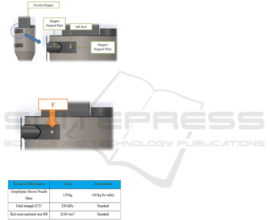
3.5 Calculation of Voltage Occurring in
BoltEd Joints
In the manufacturing process of the geopolymer
mortar nozzle construction, the connection on the
hopper support plate must be considered, because this
plate will hold the nozzle of the geopolymer mortar.
This plate relates to the hopper nozzle using the
method of splicing nuts and bolts M8.
Figures 8: Bolt joints on the Hopper support plate.
3.5.1 Load/Voltage on M8 Bolts
Figures 9: The direction of force occurring on the M8 bolts.
Known:
Figure 10: M8 bolt information table.
find:
a) Permissible voltage
b) Maximum load of bolts
c) Voltage on the bolts
Answer:
1) Determining the Clearance Voltage
σ permissions = Re/Sf (3)
= 250 / 1.5
= 167 N/mm
2
τ permissions = 0.7 x σ permissions
= 0.7 x 167 N/mm
2
= 117 N/mm
2
Information:
σizin= Tensile voltage/normal clearance ( N/mm
2
)
τizin= Clearance shear stress ( N/mm
2
)
Re= Resistant extension ( N/mm
2
)
Sf= Safety factor
Safety Factor for static loading = 1.2 – 2
2) Maximum load bolts M8
τ= F / A (4)
F= τ x A (5)
= 117 x 32.84
= 3842 N
Description:
τ= Shear stress ( N/mm
2
)
A= Cross-sectional area ( mm
2
)
The force of the geopolymer mortar nozzle is 1100 N,
it can be determined that 1 bolt M8 is able to
withstand the load of the geopolymer mortar nozzle.
However, due to several considerations, namely
extreme weather factors and natural disasters such as
earthquakes, 4 M8 bolts were used.
3) Determining the shear stress that the bolt
receives
F = 1 100 N
F = 1 nz100 N / 4 = 275 N (Loading divided on 4
bolts)
τ= F / A (6)
= 275 N / 32.84 mm
2
= 8.4 N/mm
2
3.6 Material Use
The procurement of materials for the construction of
geopolymer mortar nozzles is divided into 2, namely
standard parts and raw materials.
3.6.1 Standart Parts
This Standard Part is obtained by buying standard
parts/components without the need to do the
machining process again, for example standard
components, namely baut and nuts. For the next
process these standard components go directly into
the assembly process.
iCAST-ES 2022 - International Conference on Applied Science and Technology on Engineering Science
846
3.6.2 Non-Standart Parts/Raw Material
This Raw Material is obtained by purchasing raw
materials, then the machining process is carried out to
get the desired shape and function according to the
working drawing.
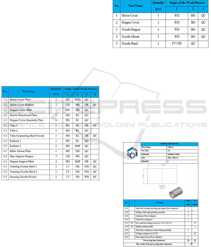
3.7 Machining Process
The machining process discusses the work of raw
materials and sub assembly parts, this machining
process includes the stages of the work process,
operation plan and quality control process. The
following is an explanation of each stage of the
machining process.
3.7.1 Stages of Raw Material Work Process
The stages of the work process are the sequence of
processes for making raw material components. The
following are the stages of work on the raw material
components of the construction of the geopolymer
mortar nozzle.
Figure 11: Stages of the raw material work process.
Information:
HG: Hand Grinding
CB: Cut Burrs
DR: Drill
LT: Lathe
QC: Quality Control
RL: Rolling
BND: Bending
SMF: Sheet Metal Forming
WD: Welding
KB: Work Bench
3.7.2 Stages of the Process of Working on
sub Assembly Parts
The following are the stages of the process of working
on the components of the sub assembly part sub
assembly construction of the geopolymer mortar
nozzle.
Figure 12: Stages of the process of working on sub
assembly parts.
Information:
HG: Hand Grinding
WD: Welding
FT+TH: Fit+Thread
QC: Quality Control
3.8 Operation Plan
Work planning is made to regulate the workprocess
to avoid mistakes and as a source of information to
calculate the estimated processing time. The
following is one of the operation plans for the
construction of the geopolymer mortar nozzle.
Figure 13: Operation Plan (OP).
The Manufacturing Process of Geopolymer Mortar Nozzle Construction on Civil Building 3D Printing Machine
847
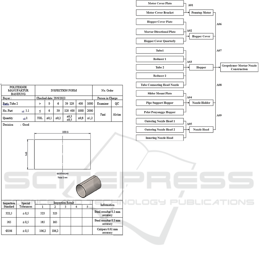
3.9 Quality Control (QC)
After carrying out the planning of the process and the
machining process. Thework that has been completed
in the process will pass the Quality Control (QC)
stage.
Quality Control aims to check that the parts that
have been made are in accordance with their
respective work drawings, if the compensatoryis not
suitable and exceeds the existing tolerances, then the
components must bere-worked or re-procured and
cannot be continued to the next process.
Figure 14: Quality control (QC).
3.10 Assembly
Assembly is the activity of combining components or
parts that have been made into a unit that has a certain
function. The components of machining, cutting and
fabrication are assembled in a manner in accordance
with the existing working drawings until all these
components become unitary and can be used
according to their functions.
The following are the stages of assembly of each
part of the construction of the geopolymer mortar
nozzle:
Diagram 2: Geopolymer mortar nozzle construction
assembly process.
3.11 Trial
After the construction of the geopolymer mortar
nozzle is completed, the next step is a trial. The trial
stage is carried out to ensure that the construction of
the geopolymer mortar nozzle can be used in
accordance with its function. At this stage, what must
be done is a trial of the production of geopolymer
material, starting with inserting a geopolymer mortar
into the nozzle hopper as much as 30 liters, then
turning the extruder by adjusting the strepper motor
at different speeds each time the test is carried out.
This aims to determine the construction ability of
the geopolymer mortar nozzle in removing
geopolymer material.
Itis hoped that after the trial
stage, data on the speed of the motror stepper and the
ideal fluid discharge will be obtained so as to produce
the best production of geopolymer material.
4 ESTIMATED TIME AND COST
4.1 Estimated Time
Etime estimation is obtained from the summation of
TNC (Time non cutting) and TC (Time Cutting) on
the operation plan. Here is the calculation of the total
iCAST-ES 2022 - International Conference on Applied Science and Technology on Engineering Science
848
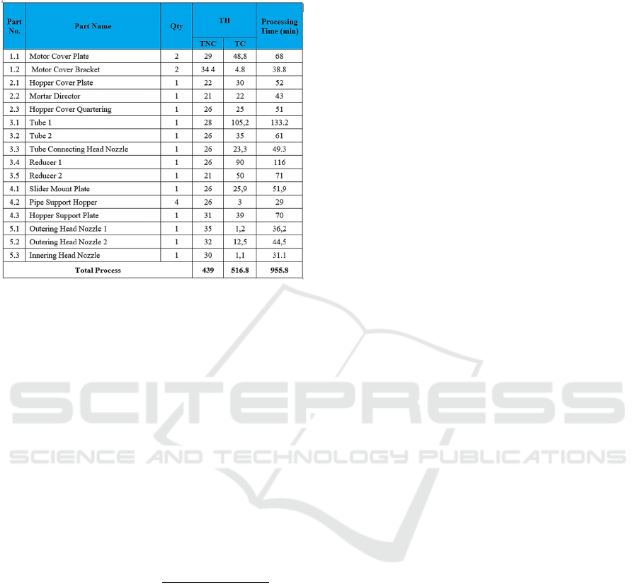
estimated time of the construction process of the
geopolymer
mortar nozzle construction:
Figure 15: Total Estimated Time.
Total machining process time:
= 955.8 minutes : 60 minutes
= 15.93 hours
7 hours = 1 working day
15.93 hours = 2.3 days ≈ 3 working days
4.2 Estimated Cost
Here is the overall cost of the manufacturing process
of geopolymer mortar nozzle construction on civil
building 3D Printing machine:
• Total Biata Raw Material Rp. 664.500,00,-
• Total Standard Part
Cost Rp. 4,500.00,-
• Total Machining Cost Rp. 497.100,00,-
• Total Operator
Fee Rp. 257.400,00,- +
• Total Cost Rp. 1.423.500,00,-
• Overhead Costs (20% x Process Costs)
Rp. 284.700,00,-
So, the total cost of the basic cost of the geopolymer
mortar nozzle
construction process on the civil
building 3D printing
machine is Rp. 1,708,200.00,-
≈ Rp. 1,708,500.00,-.
5 CONCLUSION
Overall, the results of the manufacturing process of
the geopolymer mortar nozzle construction on the
civil building 3D printing machine can be concluded
as follows:
1. The process of making geopolymer mortar
nozzle construction produces designs, work
drawings and manufacturing process planning
which are used to reference the manufacturing
process of Geopolymer Mortar Nozzle
Construction on Civil Building 3D Printing
Machines.
2. The working principle of this tool is that the
geopolymer mortar accommodated in the hopper
nozzle will move down due to the force of gravity
and the large expenditure of the geopolymer
mortar is regulated by the extruder driven by the
stepper motor.
3. In the process of making Geopolymer Mortar
Nozzle Construction on the Civil Building 3D
Printing Machine, this includes observation,
manufacturing planning, machining and
fabrication ice pros, assembly planning and trial
planning. The machining process includes a lathe
and a drill. The fabrication process includes
cutting grinding, hand grinding, drilling, Sheet
Metal forming, bending, rolling, and welding.
4. The total estimated time required in the
construction process of the geopolymer mortar
nozzle is 15.93 hours and the total estimated cost
of the geopolymer mortar nozzle construction
process is Rp. 1,700,500.00,-.
REFERENCES
Elemen Mesin 3 Perhitungan Elemen Mesin:
Politeknik Manufaktur Negeri Bandung.
Goeritno Wahjoe; Wikanda Uli; dan S. Ecep. 2000. Standar
Polman Seri 0. Bandung: Politeknik Manufaktur Negeri
Bandung.
Waloeyo, Gamawan A. 2021. Biaya Dasar PPC,
Bandung: Politeknik Manufaktur Negeri Bandung.
Anonim, Elemen Mesin 1
Anonim, Elemen Mesin 2
The Manufacturing Process of Geopolymer Mortar Nozzle Construction on Civil Building 3D Printing Machine
849
