Voter based Control for Situation Awareness
and Obstacle Avoidance
David Sanders
1
, Giles Tewkesbury
1
, Malik Haddad
2
, Shikun Zhou
1
and Sergey Khaustov
1
1
Faculty of Technology, University of Portsmouth, Anglesea Road, Portsmouth, U.K
2
Northeastern University – London, St. Katharine’s Way, London, UK
Keywords: Voter Based, Control, Situation Awareness, Obstacle, Avoidance.
Abstract: Situational awareness and obstacle avoidance for a powered wheelchair are considered. A voter-based control
system uses the results from a path planner, sensors and image processing algorithms. A route planning system
utilizes interval analysis, and image processing algorithms are used for obstacle detection. Voter based control
is adapted from their results.
1 INTRODUCTION
The architecture of a situational awareness system for
a navigation system is presented. The system can be
divided into two main parts: obstacle detection and
collision avoidance. The collision avoidance system
includes two major components, a higher-level route
planning module and a lower-level reactive sub-
system.
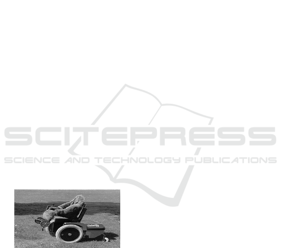
A Bobcat II Wheelchair was selected as a platform
for the research. An image of the powered wheelchair
is shown in Figure 1.
Figure 1. Bobcat II Wheelchair.
The current state of the art for situational
awareness for vehicles is briefly discussed in the
following Section, mainly based on Liu et al (2016)
and Friebe et al (2018). The software architecture of
the situational awareness, collision avoidance and
control system is described in Section 3.
Various sensors and controllers could be attached
to the microcomputer and therefor the wheelchair.
Simple and reliable Ultrasonic sensors (Sanders et al,
2016, 2018 and 2019) and a forward-looking camera
were used in this research. An on-board
microcomputer collected and processed signals from
the sensors and joystick for controlling the two
wheelchair motors. A GPS module provided position,
direction and speed data. The camera had a field of
view of 25° horizontally and 19° vertically. The
image was processed to estimate the amount of
navigable space available for choosing a course
within the field of view. The algorithms are described
and results for test images are illustrated in Section 4.
The higher-level path planning module used
interval analysis methods. Sets of waypoints were
planned for a wheelchair route. The algorithm
together with its simulation results and analysis are
presented in Section 5. Close range objects and the
visible navigable space extracted and interpreted
from the captured images were used as an input into
the lower-level reactive system integrated with the
navigation system through a voter-based mechanism.
The voter-based system was similar to that described
by (Less’ard-Springett et al, 2017), but was adapted
to utilize the output from the image processing system
based on (Friebe et al, 2018). This development with
corresponding simulation results are discussed in
Section 6. Further experimental results and
evaluations are included in Section 7. Section 8
presents conclusions and future work.
104
Sanders, D., Tewkesbury, G., Haddad, M., Zhou, S. and Khaustov, S.
Voter Based Control for Situation Awareness and Obstacle Avoidance.
DOI: 10.5220/0011903900003612
In Proceedings of the 3rd International Symposium on Automation, Information and Computing (ISAIC 2022), pages 104-109
ISBN: 978-989-758-622-4; ISSN: 2975-9463
Copyright
c
2023 by SCITEPRESS – Science and Technology Publications, Lda. Under CC license (CC BY-NC-ND 4.0)
2 SITUATIONAL AWARENESS
AND OBSTACLE AVOIDANCE
Guidance techniques were classified by Lui et al
(2016) as global path planning, local path planning
and hybrid path planning. Global path planning used
optimization methods such as Genetic algorithm, or
heuristic search algorithms such as A*. Cost
functions have included spatiotemporal
characteristics, collision probability estimates, fuel
consumption and weather influences. Local path
planning included line-of-sight and potential field
methods. Hybrid path planning combined global and
local path planning, often utilising hierarchical
architectures.
Methods can be classified as: (1) Protocol-free
collision avoidance does not have any direct rules but,
uses differential equations, level sets and optical
flow; (2) Protocol-based collision avoidance adapts
sets of rules for example A* and velocity obstacles.
Furthermore in Lin et al 2016, environment
perception methods and sensors were classified as
active or passive depending on whether the methods
counted transmitting signals or not. Passive methods
include monocular vision, stereo vision, and Infrared
vision. Visible light-based systems generally have a
long range and consume less energy. However, range
is affected by conditions such as light (for example
direct sunlight), rain or fog. Active perception
methods include Ultrasonics, LIDAR, Radar, and
Sonar. Sonar was a valuable tool for detecting hard
obstacles and helping to find safe routes.
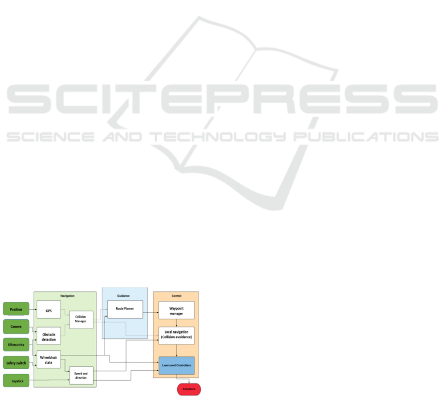
3 SOFTWARE ARCHITECTURE
The control system used a message-based
architecture for communication between threads
responsible for sensor readings, communication,
control and command execution. Figure 2 shows an
overview of the software architecture for situational
awareness and obstacle avoidance.
Figure 2. Software Architecture.
Sensor information was fed into the Collision
Manager, a global state representation of obstacles
and interacting structure. Interpretation is described
in Section 5. The Collision Manager processed the
message-based system, and contained protected data
to be shared between threads. The combination with
Mission planning information was achieved in the
higher-level Route Planner described in Section 4.
The output from the Route Planner was a new set of
waypoints, which were fed into the Waypoint
Manager. The Local Navigation Module controlled
the target course provided by a joystick or from a pre-
set route which was implemented by means of a voter
based control system [6]. The image from the camera
and the ultrasonics information, both stored in the
Collision Manager, were used for collision avoidance
which is described in Section 6.
4 HIGHER LEVEL ROUTE
PLANNING
Higher-level route planning adjusted the route
defined by the waypoints to avoid collisions and
ensure the route remained within a safe area. The Safe
Areas were predefined based on static information
about the environment, for example positions of walls
and doors etc. The route Planner read the list of
waypoints and checked if there was a risk of collision.
If a potential risk was identified, the Route Planner
modified the list of waypoints by justifying the
positions of affected waypoints or adding new
waypoints to avoid possible collisions, ensuring a
safe route. Possible collisions were calculated by
linearly extrapolating the trajectory of the wheelchair
based on its speed and direction. The algorithm was
applied in two main steps that were repeated for each
trajectory segment and the trajectory between
waypoints. The first step was to detect any possible
collisions. If there was a chance of impact, then the
path planning step was triggered. Interval analysis
allowed the set of all feasible velocities to be
determined, that is all velocities that allowed the
wheelchair to stay within a Safe Area. This set was
computed using a paving method. Secondly, the
velocity closest to the initial velocity of the
wheelchair was selected and used to calculate new
waypoint coordinate(s).
4.1 Collision Detection
The collision detection algorithm was based on
(Jaulin and Le Bars, 2013). Interval analysis provided
Voter Based Control for Situation Awareness and Obstacle Avoidance
105

tools to find solutions to the sets of inequalities and
equations. Some assumptions were made in order to
implement the algorithm. The area of movement for
the wheelchair was approximated by a 2-D plane with
a fixed Cartesian frame Oxy. The joystick provided
demanded speed, and direction while the GPS
measured speed, direction and position at time t = 0
with a known accuracy. For calculating future
positions, the speed and direction were considered as
constants. Uncertainty was handled by interval
analysis which was a key part of the approach. It was
assumed that the segments of trajectory was linear:
(t) = a
0
t + b
0
(1)
The vector b
0
is the initial position, and the vector a
0
is determined by the speed and line to be followed,
that is by two consecutive waypoint positions.
Waypoints were expressed in the fixed Cartesian
frame of the two-dimensional plane. In a first
approximation, the initial position was set to the first
waypoint. Some estimates of the velocity on the
trajectory segments were also carried out. It was
possible to make an estimation of the velocity over a
trajectory segment. In Jaulin and LeBars, 2013, they
proposed a method based on interval analysis to show
that a trajectory was accurate. The trajectory was
examined for possible collisions in a time interval [0,
tmax].
∃𝑖 ∈ {1, … 𝑚}, ∃𝑡 ∈ [0,𝑡𝑚𝑎𝑥], m
i
(t) = m
0
(t)
(2)
That is, if the following system has a solution:
{(𝑎
0
− 𝑎
𝑖
).𝑡 + 𝑏
0
− 𝑏
𝑖
= 0, 𝑡 ∈ [0,𝑡
𝑚𝑎𝑥
], 𝑖 ∈ [1, …
𝑚], 𝑎
0
∈ [𝑎
0
], 𝑎
𝑖
∈ [𝑎
𝑖
], 𝑏
0
∈ [𝑏
0
], 𝑏
𝑖
∈ [𝑏
𝑖
]
(3)
Expressed using interval analysis, this gives:
(4)
To check for collisions between waypoints,
tmax was chosen so that the wheelchair reaches the
second waypoint at tmax. An estimate of tmax was
based on estimates of velocity between waypoints.
For the case of several reference positions
(waypoints). The collision detection scheme was
applied for each segment if there are more than one
waypoint. Initial positions of waypoints were updated
to correspond to the estimated values at the beginning
of each new trajectory segment.
4.2 Detecting Crossing of Safe Areas
A Safe Area was modelled as a number of polygons
providing borders that the wheelchair should not
cross. Each polygon was modelled by the list of the
coordinates of its vertices. These coordinates were
expressed in the fixed Cartesian frame in the two-
dimensional plane. The crossing of borders algorithm
was based on the example presented in (Rosenblatt,
2010). Considering two boxes Abox and Bbox. Abox
is the initial position of the wheelchair, and Bbox is
the target position. The ith vertex of a polygon is
denoted by Vi. Let [A,B] denote the set of all the
segments with an endpoint in A and an endpoint in B.
For each polygon of the Safe Area, it was necessary
to examine if:
∀𝑖, ∀𝑆 ∈ [𝐴, 𝐵], [ ,+1 ] ∩ 𝑆 = ∅
(5)
If this condition was true for all sides of all polygons,
the wheelchair never crossed a Safe Area border. A
simplified approach was used to implement this. An
easier implementation was used. The contrapositive
was considered instead and the corresponding
relations were:
∃𝑖, { ∃𝑆 ∈ [𝐴, 𝐵], (𝑉
𝑖
, 𝑉
𝑖+1
) ∩ 𝑆 ≠ ∅ 𝑎𝑛𝑑
∃𝐷 ∈ (𝐴, 𝐵), [ , 𝑉
𝑖+1
] ∩ 𝐷 ≠ ∅ 𝑎𝑛𝑑
[𝑉
𝑖
∪ 𝑉
𝑖+1
] ∩ [𝐴 ∪ 𝐵] ≠ ∅
(6)
Let (A,B) denote the complete set of lines
supported by a point in A and a point in B, (Vi, Vi+1)
the line supported by Vi and Vi+1, [Vi, Vi+1] the
segment linking Vi and Vi +1, and [A∪B] and [Vi
∪ Vi +1] the smallest box including A and B or Vi
and Vi +1 respectively. The last condition is
important for a special case, where all the points are
aligned. In that special case, the two first conditions
will be true even if the trajectory does not cross the
polygon side. The first two conditions are not
implemented directly, instead the equivalence in
(Friebe et al, 2018) was used. If that was true for one
of the polygons of the Safe Area, then the trajectory
of the wheelchair would cross the border determined
by the polygon.
4.3 Path Planning
Interval analysis was used for path planning. The set
of all velocities that allowed the wheelchair to avoid
collisions was computed to ensure it stayed within the
Safe Area. Separator algebra was adopted.
A separator is an interval analysis tool that aims
to approximate the solution set of an equation. A
ISAIC 2022 - International Symposium on Automation, Information and Computing
106
separator corresponding to the collision condition of
each obstacle, and to the crossing condition of each
side of each polygon of the Safe Area was
constructed. Secondly, the convolution of all the
separators was computed. Finally, the set of all the
feasible velocities was computed with a paving
method. In result, the velocity closest to the initial
velocity of the wheelchair was chosen. This velocity
was stored as the time when it would take the
wheelchair to reach a waypoint with its previous
velocity. This assumption allows the computation of
a new waypoint which replaced the former one. To
build the collision separators, the same conditions as
for the detection part were used. In order to express
these constraints as sets the following reformulation
was used: ∃𝑖 ∈ {1, … 𝑚},
{[
𝑏
i
𝑥
] − [
𝑏
0
𝑥
]
∈
([
𝑎
0
𝑥
] − [
𝑎
i
𝑥
])
∗
[0,
𝑡
𝑚𝑎𝑥
]
𝑎𝑛𝑑
[
𝑏
𝑦𝑖
] − [
𝑏
0
𝑦
]
∈
([
𝑎
0
𝑦
] − [
𝑎
i
𝑦
])
∗
[0,
𝑎
𝑥
]
𝑎𝑛𝑑
([𝑏
i𝑦
] − [𝑏
0𝑦
]) ∈ ([𝑎
0𝑦
] − [𝑎
i𝑦
]) ([𝑎
0𝑥
] − [𝑎
i𝑥
]) ∗
([𝑏
i𝑥
] − [𝑏
0𝑥
]
(7)
For separators representing Safe Area border
crossings, the same conditions as for the detection
step could not be used. The two first conditions could
be used, but not the third because it was a logical
relation, and separators dealt with sets or arithmetic
relations. The third condition was given by:
∃𝑖, [𝑉
𝑖
∪ 𝑉
𝑖
+1] ∩ [𝐴 ∪ 𝐵] ≠ ∅
(8)
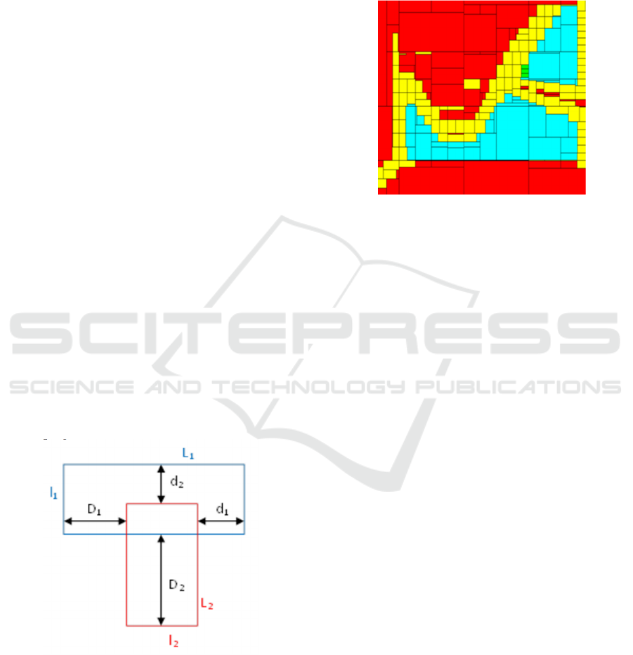
This condition was true if the two boxes were
overlapping. Figure 3 illustrates an example of two
overlapping boxes.
Figure 3. Two overlapping boxes (Friebe et al, 2018).
Let [Vi ∪ Vi+1] represent the blue (upper) box, and
[A∪B] the red (lower).
The two boxes are overlapping if:
{max(
𝑑
1
,
𝐷
1
)− max(
𝐿
1
,
𝑙
2
) ≤ 0
(9)
𝑎𝑛𝑑
max(
𝑑
2
,
𝐷
2
)−max(
𝑙
1
,
𝐿
2
) ≤ 0
(10)
A paving of the set of feasible velocities,
represented on the (Vx, Vy) plane, is illustrated in
Figure 4.
Figure 4. Result of the paving process.
In this simulation, there were three obstacles, and the
Safe Area was defined by a square around the
evolution area of the wheelchair. Speeds from 0 to
0.5m/s on Vx and Vy were explored. The red
segments are inside the set of velocities that may lead
to a collision or border crossing. The yellow boxes are
on the border of this set. The light blue boxes are
outside this set and represent a set of feasible
velocities. The green box is the velocity selected by
the algorithm.
5 IMAGE PROCESSING
The image ahead of the camera was constructed from
the ultrasonic sensors and the camera. Software
handling camera frames was based on the computer
vision library OpenCV. Pattern identification was
used and targeting free space rather than potential
obstacles. The navigation system was able to select a
best route. Each frame was processed independently
while the video handle was open.
First the algorithm checked if the camera was
calibrated. If a green square was found, the thread
was halted until calibration had finished. Second,
frames were fed into a Gaussian filter to eliminate
noise and through a Canny filter to outline objects’
contours. Then, the system defined a specific Region
of Interest, excluding every part of the frame falling
on the upper zone as the distance was negligible.
The frame was analysed column by column using
a column width equal to 1° of bearing, clustering
contours to detect obstacles; iterating from the bottom
Voter Based Control for Situation Awareness and Obstacle Avoidance
107

left corner to the top right corner, external elements
identified were pushed to the Collision Manager to
bridge the Obstacle Detection node with the Local
Navigation node, using the voter system.
Time of flight served as a measurement of the
distance between sensors and obstacles. Sixteen
independent active channels were used for
simultaneous acquisition arranged with a 90° field of
view. The module was mounted at the front of the
wheelchair between the footrests. The accuracy of
the sensor system could allow for precise object
identifications in the future.
6 ADAPTATION OF THE VOTER
BASED CONTROL SYSTEM
Voter based systems were first developed at Carnegie
Mellon University in the mid-1990s (Rosenblatt,
2010) and have a long history of real-world
applications (Larson et al, 2007). The Wheelchair
used a voter-based control system for navigation and
obstacle avoidance. Each voter had a specific
objective that was translated into votes for the
possible target courses of the wheelchair. The voter-
based control system enabled separation of concerns
and modularity. The voters were:
1. Waypoint-Voter - movement towards waypoint.
2. Manoeuvre-Voter - staying on the same course
to avoid unnecessary manoeuvres
3. Channel-Voter - staying within the channel
between two consecutive waypoints.
4. Proximity-Voter - avoiding close obstacles.
The votes were combined to decide the target course.
The visual field representation of the image camera in
the Collision Manager was used in the Proximity-
Voter to react to potential collisions.
6.1 Free Space in the Visible Field from
the Camera
The amount of free space in the visible field of the
camera was added to the Collision Manager with the
wheelchair’s current heading. In the Collision
Manager, that information was inserted into a map
where absolute bearing values were mapped to free
space. The lower and higher limits for the currently
visible field were also stored. Thus, if the wheelchair
turned, a larger number of bearings would be
available in the map, than those currently within the
field of view. When a map value had not been updated
for a set amount of time, the amount of free space at
the bearing was gradually increased. After an
additional amount of time, map values were
considered outdated and would be deleted. In the tests
described below, the time threshold to start increasing
the free space was 5s, and the time threshold for
deletion of old values was 10s. collisions.
6.2 Adaptation to Proximity-Voter
A number was given for each course in the camera’s
field of view. That represented the relative distance
of obstacle free space in a particular direction.
Proximity-Voter used that information to calculate
votes: Votes decreased in areas outside the current
field of view; and if an obstacle was visible in a
direction, votes were decreased for that direction. The
decreasing rate depended on the relative distance of
free space:
𝑣𝑜𝑡𝑒𝐴𝑑𝑗𝑢𝑠𝑡
=
𝑘∗
(100−
𝑟𝑒𝑙𝑎𝑡𝑖𝑣𝑒𝐹𝑟𝑒𝑒𝐷𝑖𝑠𝑡𝑎𝑛𝑐𝑒
)/ 100 (11)
where k was a weighting factor.
The adjacent directions within a range of
adjacentLimit degrees were also decreased.
𝑑𝑖𝑟𝑒𝑐𝑡𝑖𝑜𝑛𝐷𝑖𝑠𝑡
=
𝑎
(
𝑑𝑖𝑟
−
𝑜𝑏𝑠𝑡𝑎𝑐𝑙𝑒𝐷𝑖𝑟
) (12)
𝑑𝑖𝑠𝑡𝑎𝑛𝑐𝑒𝐹𝑎𝑐𝑡𝑜𝑟
=(
𝑎𝑑𝑗𝑎𝑐𝑒𝑛𝑡𝐿𝑖𝑚𝑖𝑡
−
𝑑𝑖𝑟𝑒𝑐𝑡𝑖𝑜𝑛𝐷𝑖𝑠𝑡
)/
𝑎𝑑𝑗𝑎𝑐𝑒𝑛𝑡𝐿𝑖𝑚𝑖𝑡
(13)
Thus, votes decreased with
𝑖𝑓
𝑑𝑖𝑟𝑒𝑐𝑡𝑖𝑜𝑛𝐷𝑖𝑠𝑡
<
𝑎𝑑𝑗𝑎𝑐𝑒𝑛𝑡𝐿𝑖𝑚𝑖
t then 𝑣𝑜𝑡𝑒𝑚𝑎𝑥 ∗
𝑣𝑜𝑡𝑒𝐴𝑑𝑗𝑢𝑠𝑡 ∗ 𝑑𝑖𝑠𝑡𝑎𝑛𝑐𝑒𝐹𝑎𝑐𝑡𝑜r (14)
Otherwise 0
(15)
If an obstacle was visible, then votes were increased
in directions 90° left and right of the obstacle.
7 TESTING AND RESULTS
The control system of the wheelchair was set up to
run on a computer simulation. Distance at closest
point of approach was given for each test case. Five
different experiments were completed with slightly
different starting positions. Minimum and mean
DCPA values were calculated. If an obstacle was
within the field of view, information was added to the
visible field representation, related to the distance to
the obstacle.
𝑑𝑖𝑠𝑡𝑎𝑛𝑐𝑒 < 𝑚𝑎𝑥𝑉𝑖𝑠𝑖𝑏𝑙𝑒𝐷𝑖𝑠𝑡𝑎𝑛𝑐𝑒 if 𝑟𝑒𝑙𝐷𝑖𝑠𝑡𝑎𝑛𝑐𝑒 =
100 ∗ 𝑑𝑖𝑠𝑡𝑎𝑛𝑐𝑒 𝑚𝑎𝑥𝑉𝑖𝑠𝑖𝑏𝑙𝑒𝐷𝑖𝑠𝑡𝑎𝑛𝑐𝑒 (16)
ISAIC 2022 - International Symposium on Automation, Information and Computing
108

Otherwise 0 (17)
This value was set for a range of adjacent bearings
proportional to
𝑚𝑎𝑥𝑉𝑖𝑠𝑖𝑏𝑙𝑒𝐷𝑖𝑠𝑡𝑎𝑛𝑐𝑒 − 𝑑𝑖𝑠𝑡𝑎𝑛𝑐𝑒
𝑚𝑎𝑥𝑉𝑖𝑠𝑖𝑏𝑙𝑒𝐷𝑖𝑠𝑡𝑎𝑛𝑐𝑒 (18)
Closer obstacles occupied a larger space in the
view. The maximum visible distance was set to 10m
in the simulation. The DCPA was increased
considerably for head-on cases, when using the
Proximity-Voter. The DCPA was lower when using
the Proximity-Voter rather than without it. The
obstacle avoidance system increased the DCPA when
obstacles were detected. A problem was experienced
with the Voter based system that has been described
in (Larson et al, 2007). It occasionally fluctuated
between two possible choices, and this could have led
to near collisions. This oscillatory behaviour was
occasionally observed. In all cases the wheelchair
avoided obstacles.
8 CONCLUSIONS AND FUTURE
WORK
Some potential problems became apparent with the
Higher-Level Route Planning algorithm. A
wheelchair user could constantly override the system,
and that affected calculated speeds towards
waypoints. Additionally, when the collision
avoidance calculation was performed for a long route,
the uncertainty box could become large.
The narrow field of view of the imager simplified
calculations but with a limitation. The algorithm
performed significantly worse when only the
currently visible information was used and detected
obstacle bearings were not stored. The calculations
needed input from the ultrasonic systems to work
properly. The wheelchair would attempt to return to
joystick controls immediately after losing sight of an
obstacle, leading to smaller DCPAs. There would be
cases where a collision could occur since the
wheelchair was unable to detect an obstacle due to the
narrow field of view. Another case could also happen
when the wheelchair was unable to detect an obstacle
in time to perform an appropriate maneuver. An
option that would improve matters slightly would be
to have a camera with a pan option that could cover a
larger field of view. LIDAR and / or Radar might be
another option.
The system always steered away from obstacles
and worked well for wheelchairs approaching from
ahead. More image processing tests are necessary in
different weather and lighting conditions.
The voter-based system worked well in collision
avoidance. The system occasionally switched
between two possible choices, potentially leading to
a near collision. To mitigate for this, Maneuver-Voter
could be modified. Currently Maneuver-Voter
increases votes slightly around the current heading to
avoid unnecessary maneuvering. An alternative could
be to increase votes around the previous selected
course as that might increase the chance that a
selected maneuver would be performed. Further
work will include the system being evaluated in
clinical trials.
REFERENCES
Friebe, A., Giammarco, R., Le Gallic, M., Rolinat, C.,
Waller, M., 2018 Situational Awareness and Obstacle
Avoidance for a Wind Propelled Marine Research
ASV. 17th Int Conf on Computer & IT Apps in the
Maritime Industries, Pavone, 14-16 May, Hamburg,
pp: 211-225. ISBN 978-3-89220-707-8.
Jaulin, L., Le Bars, F., 2013 A simple controller for line
following of sailboats, Robotic Sailing 2012, Springer,
pp.117-129.
Larson, J., Bruch, M., Halterman, R., Rogers, J., Webster,
R., 2007 Advances in Autonomous Obstacle
Avoidance for Unmanned Surface Vehicles, Defense
Technical Information Center.
Less’Ard-Springett, J., Friebe, A., Le Gallic, M., 2017
Voter based control system for collision avoidance and
sailboat navigation, Robotic Sailing, Springer, pp.57-
68.
Liu, Z., Zhang, Y., Yu, X., Yuan, C., 2016 Unmanned
Surface Vehicles: An overview of 225 developments
and challenges, Annual Reviews in Control, Elsevier
41, pp.71-93.
Rosenblatt, J., 2010 DAMN: A distributed architecture for
mobile navigation, J. Experimental & Theoretical
Artificial Intelligence 9:2-3, pp.339-360.
Sanders, D., 2016 Using self-reliance factors to decide
how to share control between human powered
wheelchair drivers and ultrasonic sensors, IEEE Trans.
Neur. Sys. Rehab., vol. 25, no. 8, pp.1221-1229.
Sanders, D., Gegov, A., Tewkesbury, G. Khusainov, R.,
2019 Sharing driving between a vehicle driver and a
sensor system using trust-factors to set control gains
Adv. Intell. Syst. Comput 868 Springer pp 1182-1195.
Sanders, D., Gegov, A., Haddad, M., Ikwan, F., Wiltshire,
D., Tan, Y., 2018 A rule-based expert system to
decide on direction and speed of a powered wheelchair
Proc. of SAI Intelligent Systems Conference (London)
pp 822-838.
Voter Based Control for Situation Awareness and Obstacle Avoidance
109
