
Intelligent Judgment of Wrong Wiring Method in Large-Scale
Training of Electrical Testing
JiaHeng Xu
*
, WeiWei Yang, Na Song, Wei Ren and Xiao Rong
Shandong Electric Power College, No. 500 South Second Ring Road, Jinan, Shandong Province, China
Keywords: Algorithm, Electrical Test, Wiring, Judgment.
Abstract: In the paper, in view of the complex wiring in the large-scale training process of electrical testing, the
trainer needs to frequently judge the wiring right and wrong status quo, and proposes an intelligent
judgment method based on the YOLO algorithm, through the logical binding of the digitized equipment
terminals and the connected wire relationship in the test, relying on the learning of standard wiring, the
automatic identification of the test connection line is realized, which greatly saves labor costs, reduces the
possibility of human error, and improves work efficiency. New ideas have been developed for the training
of new employees to conduct large-scale voltage transformer error tests.
1 INTRODUCTION
Electrical test is an important means for the power
grid company to judge the status of electrical
equipment, good or bad, but also a new employee
must master a class of important skills, in the
training process, the trainer needs to constantly
check whether their wiring is correct or not, due to
the large amount of training, the trainer in the
inspection process will inevitably appear paralyzed,
visual fatigue, resulting in low efficiency, there is
such or that error, which brings greater safety risks
to the training process, for this reason, The author
proposes an automatic determination method for
electrical test wiring based on YOLO algorithm,
which greatly improves the labor efficiency of
wiring inspection, reduces the possibility of false
positive, and thus ensures the safety of the training
process. Below we take the field test of current
transformer as an example to illustrate the
application of this method.
2 TEST METHOD FOR ERROR
OF CURRENT TRANSFORMER
The current transformer error test is using the
comparative method, in order to measure the error of
the current transformer under test, it is necessary to
use a standard current transformer with a high
accuracy level, compared with the test product, in
the rated load and the lower limit load of the two
cases, respectively, the error of the current
transformer under test is measured, and the specific
wiring is shown in Figure 1.
3 DESIGN IDEAS
Based on YOLO V4 target detection, intelligent
barcode recognition, and data intelligent verification
technology, an intelligent judgment system for
misconnection of current transformer field error test
is developed.
3.1 Digital Preprocessing
3.1.1 Digitization of Test Equipment
All the test equipment participating in the test, paste
the equipment asset code, and enter the equipment
information and barcode into the system through the
data acquisition terminal that supports the camera
function (hereinafter referred to as the acquisition
terminal).
Xu, J., Yang, W., Song, N., Ren, W. and Rong, X.
Intelligent Judgment of Wrong Wiring Method in Large-Scale Training of Electrical Testing.
DOI: 10.5220/0011909500003613
In Proceedings of the 2nd International Conference on New Media Development and Modernized Education (NMDME 2022), pages 229-234
ISBN: 978-989-758-630-9
Copyright
c
2023 by SCITEPRESS – Science and Technology Publications, Lda. Under CC license (CC BY-NC-ND 4.0)
229

Figure 1: Wiring diagram of current transformer error test.
Seven devices are used in Figure 1, namely
power supply box, voltage regulator, lifting current
instrument, standard current transformer, current
transformer tested, load cases and transformer
calibrators, using a total of 16 wires, including 12
secondary wires, 3 grounding wires, and 1
high-current wire. A total of 16 pairs of terminals are
involved, of which wire 1K1-1S1 and wire 1K1-K
share a terminal 1K1.
3.1.2 Digitization of Test Equipment
Terminals
Digitize the terminals of the test equipment, adopt
the recording method of pasting a two-dimensional
code, and enter the system
through the acquisition
terminal, hereinafter referred to as the terminal
code, and the terminal code is bound to the test
equipment code, as shown in Figure 2 and Figure
3.
Caliator terminal T
0
Caliator terminal
K
Caliator terminal T
X
earth terminal
Figure 2: Terminal code.
Figure 3: Device terminal code digitization.
3.1.3 Digitization of the Terminals of the
Device Tested
The terminals of the tested transformers are
digitized, and the recording method of sticking
codes is adopted. The terminal codes of the
transformers are bound to the equipment codes of
the transformers and are entered into the system
through the acquisition terminal, as shown in Figure
4 and Figure 5.
Figure 4: Device primary terminal code digitization.
NMDME 2022 - The International Conference on New Media Development and Modernized Education
230
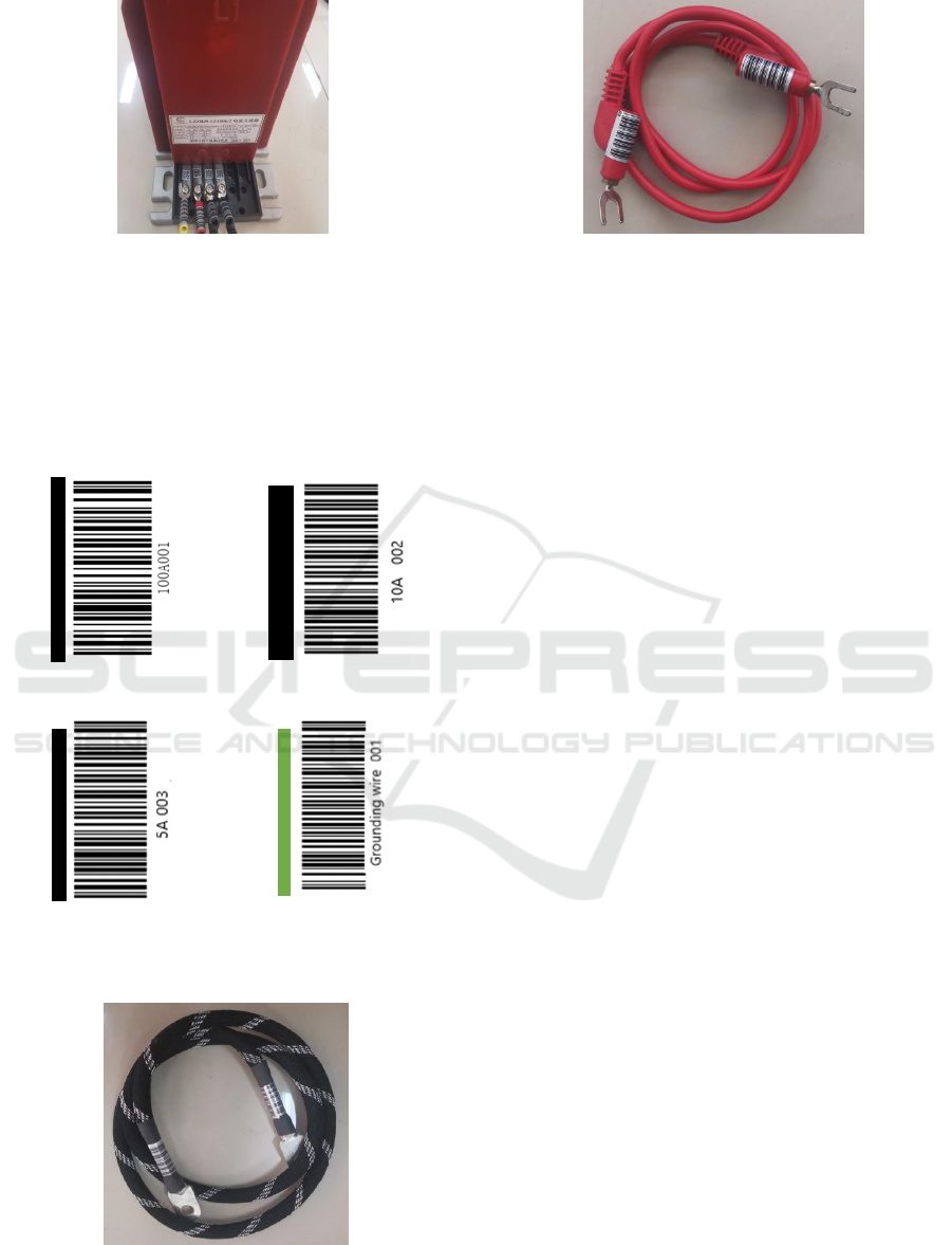
Figure 5: Device secondary terminal code digitization.
3.1.4 Digitization of Test Lines
The two terminals of the test line are coded in rings,
used in pairs, and entered into the system through
the acquisition terminal, as shown in Figure 6,
Figure 7 and Figure 8.
Current line lo
g
o 1 Current line lo
g
o2
Current line lo
g
o 3 Groundin
g
wire lo
g
o 1
Figure 6: Test line labeling digitization.
Figure 7: Digitization of the primary line.
Figure 8: Secondary line digitization.
3.2 Terminal Wiring Detection
The target detection method of YOLO v4 is adopted,
the terminal and wiring are set as the target
recognition area, multiple barcodes in each
recognition frame are collected, and the barcode
image is processed by the image processing function
of the collection terminal, and the computer reads
the image in the image file format, and then identify
them after image preprocessing (Redmon 2016,
Bochkovskiy 2020), bind the interconnected
terminal codes and line labels, identify the terminal
codes and single or multiple line labels in the area,
and record them in the temporary database.
In this way, all terminals are photographed and
identified in turn, and all terminal codes and the
corresponding wire labels of the terminals are
identified in turn, and recorded in the comparison
library. Here, YOLOv4 is required to intelligently
distinguish the mutual binding relationship between
different terminals and line labels (Yu 2019).
3.3 Architecture of the Algorithm
For a target detection algorithm, it can usually be
divided into 4 general modules. The YOLOv4
model includes the input end. CSPDarknet53 is used
as the benchmark network BackBone, SPP is used as
the additional module of Neck, PANet is used as the
feature fusion module of Neck, and YOLOv3 is used
as the Head. The network structure analysis diagram
is shown in Figure 9.
Intelligent Judgment of Wrong Wiring Method in Large-Scale Training of Electrical Testing
231
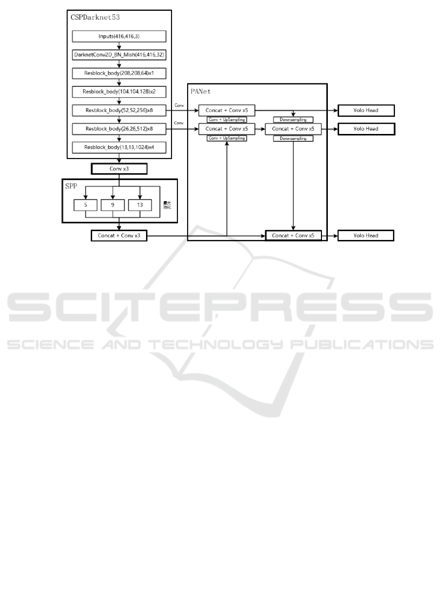
Figure 9: Analysis of YOLOv4 network structure.
The input side refers to the picture representing
the input. This stage usually includes an image
preprocessing stage, that is, scaling the input image
to the input size of the network, and performing
operations such as normalization. In the network
training stage, YOLOv4 uses Mosaic data
enhancement operations to improve the training
speed of the model and the accuracy of the network;
it uses cmBN and SAT self-adversarial training to
improve the generalization performance of the
network;
The benchmark network is usually a network of
classifiers with excellent performance, which is used
to extract some general feature representations.
YOLOv4 uses CSPDarknet53 as the benchmark
network. On the one hand, Concat is used instead of
Add to extract richer features. After the Concat
operation, the size of the feature map will remain
unchanged, and the depth will increase, while the
size and depth will not change after the Add
operation. In this sense, using Concat instead of Add
can extract richer features. On the other hand, the
transition layer (1 * 1conv + 2 * 2pooling) is
introduced to extract features, reduce the amount of
calculation, and improve the speed. Another point is
to fuse the Base layer into two parts to extract richer
features. Divide the Base layer into two parts, and
perform the Concat operation on one part of the
output obtained through a similar residual network
and the other part, and pass the result of the
operation through the Transition Layer.
In fact, CSPNet is based on the idea of Densnet,
copying the feature map of the base layer, and
sending a copy to the next stage through the dense
block, thereby separating the feature map of the
base layer. This can effectively alleviate the
gradient vanishing problem (it is difficult to reverse
the lost signal through a very deep network),
support feature propagation, and encourage the
network to reuse features, thereby reducing the
number of network parameters.
The Mish activation function is used to replace
the original RELU activation function; a Dropblock
block is added to this module to further improve the
generalization ability of the model.
The Neck network is usually located in the
middle of the benchmark network and the head
network, and it can be used to further improve the
diversity and robustness of features. YOLOv4 uses
the SPP module to fuse feature maps of different
scales. The full name of SPP is Spatial Pyramid
Pooling, that is, spatial pyramid pooling. The
purpose of using in YOLOv4 is to increase the
receptive field of the network; using the top-down
FPN feature pyramid and self- The bottom-up PAN
feature pyramid is used to improve the feature
extraction capability of the network. PANet (Path
Aggregation Network) is used instead of FPN for
parameter aggregation to be suitable for target
NMDME 2022 - The International Conference on New Media Development and Modernized Education
232
detection at different levels. The method used in the
PANet paper is Addition, and the YOLOv4
algorithm will The fusion method was changed from
addition to Concatenation.
Head output - Head is used to complete the
output of target detection results. For the detection
head part, YOLOv4 continues to use the detection
head of the YOLOv3 algorithm (Cao 2021). For
different detection algorithms, the number of
branches at the output end varies, usually including a
classification branch and a regression branch.
YOLOv4 uses CIOU_Loss to replace the Smooth L1
Loss function, and uses DIOU_nms to replace the
traditional NMS operation, thereby further
improving the detection accuracy of the algorithm.
All equipment, terminals, and connecting wires
are made with QR codes or barcode digital labels.
OPENCV is combined with cameras to collect the
target area, interpret the QR code information on the
collected photos, and bind the information
accordingly. Log into a temporary database.
The data detection function interprets the photos
detected by YOLOv4 that need to be judged by the
QR code interpretation algorithm, and compares the
interpreted information with the binding relationship
in the previous database to determine whether the
wiring is wrong.
4 DESIGN OF INTELLIGENT
JUDGMENT SYSTEM FOR
TRANSFORMER WIRING
The core of this paper is to realize the intelligent
judgment system of transformer wiring. First,
through the image (video) acquisition equipment,
combined with the YOLOv4 target detection
algorithm, set the target recognition area, and collect
the barcodes of all equipment, terminals and wiring
(Gao 2021); then use the computer to check the
barcodes. Perform identification and analysis to
obtain relevant information and record it in a
temporary database for relational binding to
determine wiring connection rules. After the picture
to be detected is sent to the system for a series of
analysis operations, the actual wiring relationship is
compared with the information in the database to
judge whether the wiring is correct and complete the
intelligent judgment of wiring.
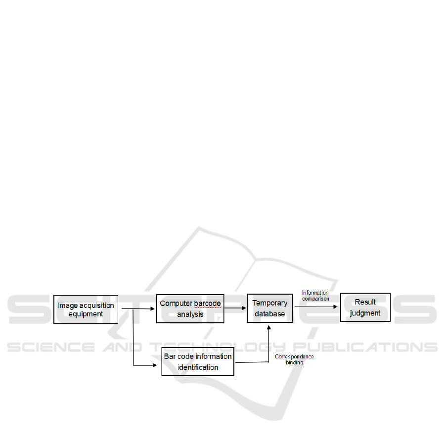
Figure 10: Flow chart of design of intelligent judgment system for transformer wiring.
Specific function realization:(1) Data acquisition
function: use microcomputer Raspberry Pi with
camera as video picture acquisition terminal, use
LINUX system, install OPENCV environment,
implant YOLOv4, barcode recognition, information
comparison and other algorithms. (2) barcode
Information binding: The barcode recognition
algorithm is implanted in the computer, the data is
locally analyzed and processed, the barcode is
parsed, and the corresponding relationship is bound
and recorded in the temporary database. (3) Data
detection function: use YOLOv4 to detect the
pictures that need to be judged, interpret the
barcodes in them, compare the interpreted
information with the database, and get the results
(Wang 2021). The process is shown in Figure 10.
The system uses a PC host as the management
platform host, which is used for information
comparison and equipment management of multiple
acquisition terminals. The test platform software
includes management platform software and
acquisition terminal. The function of the
management platform is to set up and manage
multiple collection terminals, and manage the
comparison data in a unified manner. The
acquisition terminal is embedded with a variety of
artificial intelligence target detection algorithms,
barcode recognition algorithms, and data intelligent
verification algorithms. It has the function of
automatically outputting assessment results, error
prompting, built-in camera and display screen,
which is convenient for handheld detection and
bracket fixed detection. The secondary development
interface is convenient for users to expand
functions.
Intelligent Judgment of Wrong Wiring Method in Large-Scale Training of Electrical Testing
233
5 WIRING INTELLIGENT
JUDGMENT APPLICATION
5.1 Learning About Standard Wiring
Standard wiring: The teacher holds the collection
terminal, identifies and scans the standard wiring
terminal code and line label code, obtains the
corresponding relationship between each wiring port,
and saves the name as the standard wiring method
(Liu 2022).
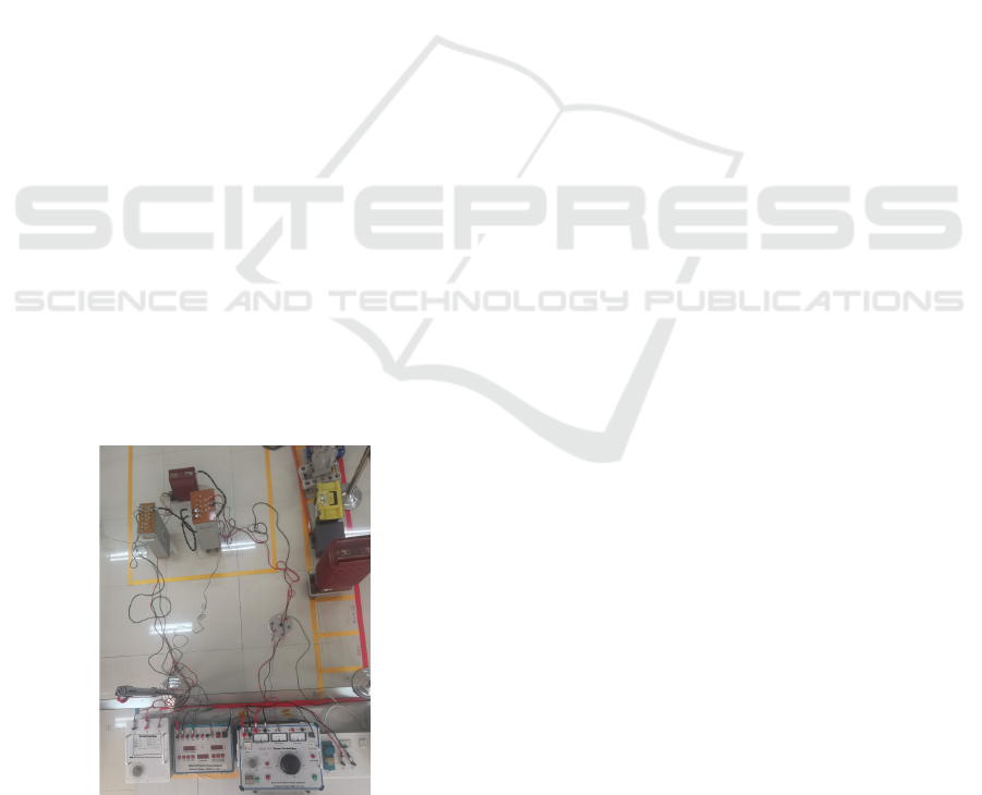
5.2 Wiring Judgment Detection
Wiring detection: Before the students connect, they
should watch the operation training video. After the
students have completed the wiring, they will hold
the acquisition terminal to perform target detection
and identification on all the test instruments and
transformers in turn, automatically capture the
equipment terminal code and line code, and detect
the unscanned data. The missing terminals will be
prompted until all scanning and verification are
completed, and the corresponding relationship
between each port will be obtained, and it will be
automatically compared with the standard wiring
method of the test item. If it is correct, it will display
"wrong wiring", and display the name of the
wrongly connected terminal, and the system will not
be powered on. This item is changed from manual
inspection by on-site teachers to intelligent
inspection by software system, the specific test
circuit diagram is shown in Figure 11, through the
experiment, the efficiency of the trainer to check the
wiring is improved, and the time is shortened.
Figure 11: Digital verification of the error test terminal of
the current transformer.
6 CONCLUSION
This project is mainly divided into two stages. The
first stage is to collect data through the acquisition
terminal and bind the corresponding relationship;
Wiring is checked. The barcode size, model
parameters, database size and other settings are
combined with the actual scene, adjusted to
appropriate values, accurately detect and identify
the target, record equipment information in time,
and conduct wiring inspection through an intelligent
detection system to improve detection efficiency
and reduce errors. The method proposed in this
paper is suitable for the automatic determination of
wiring of various electrical tests. especially when it
comes to training projects, which can greatly reduce
labor intensity and misjudgment rate, and improve
the labor efficiency of users.
REFERENCES
Bochkovskiy A, Wang C Y, Liao H Y M. YOLOv4:
Optimal Speed and Accuracy of Object Detection[J].
Computer Vision and Pattern Recognition,
2020,17(9): 198-215.
Cao Chunjian, Zang Qiang, Wang Zejia, et al. Improved
YOLOv3 target detection algorithm [J]. Chinese
Science and Technology Papers,
2021,16(11):1195-1201.
Gao Xinbo, Mo Mengjingcheng, Wang Haitao, etc.
Research progress of small target detection [J]. Data
Collection and Processing, 2021, 36(3): 391-417.
Liu Xinyu. Research on image target detection algorithm
based on YOLO deep learning model [J]. Computer
Programming Skills and Maintenance,
2022(7):131-134.
Redmon J , Divvala S , Girshick R , et al. You Only Look
Once: Unified, Real-Time Object Detection[J]. IEEE,
2016:779-788.
Wang Miao, Zhang Longxin. Image fault detection of
train locking plate based on YOLOv4 [J]. Modern
Information Technology, 2021, 5(20): 42-43, 49. DOI:
10.19850/j.cnki.2096-4706.2021 .20.012.
Yu Xiuping, Lv Shuping, Chen Zhitao. Multi-class target
recognition based on YOLO algorithm [J]. Laboratory
Research and Exploration, 2019,38(3):34-36,76.
NMDME 2022 - The International Conference on New Media Development and Modernized Education
234
