
Stability of Circular Toroidal Shell Subjected to Uniform External
Pressure
Chengyuan Zhou and Shijie Su
Jiangsu University of Science and Technology, Zhenjiang, Jiangsu 212003, China
Keywords: Circular Toroidal Shell; Stability; Numerical Calculations; Shell Unit; Solid Unit.
Abstract: In this paper, the theoretical and numerical analysis methods for the stability of circular torodial shells under
external pressure are studied. Effects of unit type, unit density and boundary condition on the stability analysis
of circular toroidal shell are discussed. A reasonable method for establishing analysis model is proposed. The
theoretical and numerical solution are compared with the experimental value. The results show that the
numerical solution is consistent with the experimental result, while the theoretical solution calculated by the
Jordan’s formula has a large deviation.
1 INTRODUCTION
The circular toroida shell structure is widely used in
various industrial fields, such as underwater pressure
shells, reservoirs, tokamak devices, etc. The circular
toroida shell solved the problem of the overall
arrangement of space and personnel connection, thus
it became the main structural form in the underwater
space station.
Since the 1960s, the problem of the bowing of the
circular toroidal
shell has begun to receive attention.
Machnig first researched the buckling problem of a
circular toroidal shell under hydrostatic pressure in
1963. L.H. Sobel by expanding the buckling
displacement component along the direction of the
ring and meridian direction as a double triangle
number (
Flügge W, and Sobel, L. H,1965), the
stability equation of the circular toroidal shell under
uniform external pressure is processed, the stress state
before buckling is obtained by the no moment
solution. Fishlowitz, et al., proved that for less thin
ring shells, the buckling mode is rotationally
symmetric and antisymmetric to the equatorial plane
(
Fishlowitz,E.G,1972). Jordan derived the formula
for calculating the critical pressure based on the DMV
equation of the shallow shell (
Jordan,P.F,1973). Cui
and Du et al researched the stability of circular
toroidal shells by means of theoretical analysis,
numerical simulation and experimental verification
(
Du , 2015; Du, 2010).
Due to the complexity of the circular toroidal shell
structure itself, for its buckling problem, there is no
comprehensive and uniform standard. With the
development of simulation technology, scientists
have begun to use more and more methods of
numerical analysis and experimental verification to
conduct study. However, due to different constraints,
unit type, unit density, mesh generation and solution
methods are chosen by operators in numerical
analysis, it will lead to the results of numerical
analysis far apart.
In this paper, the stability of the circular toroidal
shell under external pressure was studied from
theoretical analysis and numerical calculation. The
buckling load prediction formula (Jordan formula) of
circular toroidal shell was analyzed and its
characteristics and applicability were studied;
numerical models of shell unit and solid unit of
toroidal shells were established to research the effects
of unit type, unit density and boundary conditions on
the stability of circular toroidal shell; different
thickness ratio t/r the circular toroidal shells were
established to analyze and compare the numerical
calculation results of the buckling load with the
calculation results of the Jordan formula.
Zhou, C. and Su, S.
Stability of Circular Toroidal Shell Subjected to Uniform External Pressure.
DOI: 10.5220/0011925300003536
In Proceedings of the 3rd International Symposium on Water, Ecology and Environment (ISWEE 2022), pages 117-122
ISBN: 978-989-758-639-2; ISSN: 2975-9439
Copyright
c
2023 by SCITEPRESS – Science and Technology Publications, Lda. Under CC license (CC BY-NC-ND 4.0)
117

2 THEORETICAL STUDY ON
STABILITY OF CIRCULAR
TOROIDAL SHELL
2.1 Structural Parameter of Circular
Toroidal Shell
A diagram of the circular toroidal shell structure is
shown in Fig. 1, P represents the static external
pressure, φ represents the meridian direction
coordinate, r is the radius of the circle midsection of
the shell, R is the distance from the center of the circle
to the axis of rotation, t is the thickness of the circular
toroidal shell, and θ is the ring direction.
(a) C-C cross-sectional view of toroidal pressure shell
(b) Top view of toroidal pressure shell
Figure 1: Diagram of the circular toroidal shell structure.
2.2 Prediction Formula of Buckling
Load of Circular Toroidal Shell
Jordan proposed the following formula to predict the
buckling load of a circular shell (Jordan, 1973):
()
()
()
1/3
7
0
2
2
2
/
0.1738
/1
a
tr
Rr
P
ν
≈Ε
−
(1)
Where E is the modulus of elasticity and ν is Poisson's
ratio.
The eight test models in reference
were calculated
using Eq. (1) (
Fishlowitz, 1972), the results of which
are shown in Table 1. Comparing the test results of
P
e
, the errors ((P
e
- P
0a
) / P
0a
*100%) are -16%, 2%, -
5%, 4%, 4%, 12%, 32%, and 9%, respectively. It can
be seen from Table 1 that the results of the P
e
and
Jordan formulas of test models 1 and 7 are quite
different because model 1 experienced a premature
partial failure due to the existence of the exhaust pipe;
while model 7 experienced a stable post-buckling
deformation due to the small value of Rt/r
2
.
Experiments show that the Jordan formula can
effectively predict the buckling load of the circular
toroidal shell under external pressure within a certain
parameter range (Jordan,1973)
Table 1: Comparison of theoretical value P
0a
and Fishlowitz
test value P
e
(Jordan, 1973).
R/r r/t t P
0a
P
e
P
e/
P
0a
1 7.94 23.3 1.092 0.068 0.057 0.84
2 3.57 24.7 2.032 0.102 0.104 1.02
3 2.34 47.7 1.461 0.029 0.028 0.95
4 2.35 23.4 2.946 0.153 0.159 1.04
5 1.37 92.7 1.092 0.009 0.009 1.04
6 1.36 48.9 2.083 0.039 0.044 1.12
71.19
105.4
0.965 0.007 0.010 1.32
8 1.19 47.5 2.134 0.046 0.050 1.09
It is worth noting that Jordan formula is sensitive
to thickness to diameter ratio of circular shells, which
is t/r, however, if the change in thickness t occurs
away from the Gaussian curvature change point
(point C in Figure 1 (a)), the fluctuation of t will have
little effect on the buckling load (Jordan,1973). And
considering the Poisson's ratio ν is in the range [0,
0.5], and the Poisson's ratio of common metal
materials is around 0.3. Therefore, the Jordan formula
is not very sensitive to Poisson's ratio.
However, Jordan's prediction formula can’t be
generalized to the scope of thick shell, because it is
based on thin shell theory (
Galletly,1995; Jordan,
1965; Jordan, 1966
); even in the scope of thin shells,
the scope of the Jordan formula is also limited, when
Rt/r
2
is small, the calculation result is necessarily
conservative (
Jordan, 1973). Therefore, it is still
necessary to analyse the stability of the circular
toroidal shell under external pressure by using
numerical analysis.
3 NUMERICAL ANALYSIS OF
STABILITY OF CIRCULAR
TOROIDAL SHELL
Considering the comparison between Fishlowitz’s
experimental and existing analysis and the
"perfectness" of the test model, the numerical
analysis model uses the parameters of the model 8 of
the Fishlowitz test. (The test value is P
e
=0.0504MPa),
the specific parameters are as follows: R=120.6mm,
r=101.3mm,t=2.134 mm,E=2240.8MPa,ν=0.4.
ISWEE 2022 - International Symposium on Water, Ecology and Environment
118

3.1 Type of Shell Unit
Creo was used to establish a three-dimensional model
of the surface structure. When modelling, the circular
toroidal shell was artificially divided into two parts
from the Gaussian curvature point, then it was
imported into ANSA for mesh division to generate an
INP file, which was finally imported into ABAQUS
(K.Hibbitt, 2006). In addition, the calculated load was
applied to the outer surface of the circular toroidal
shell with a uniform pressure. Three-dimensional
model and meshing are shown in Figure 2.
Figure 2: Three-dimensional model and meshing.
In theory, the circular toroidal shell is
unconstrained under external pressure, in order to
eliminate the rigid displacement of the model without
hindering the relative deformation (
Jian Zhang,
2015
), this paper referred to the Chinese ship
classification society's constraint on the spherical
shell and the reference
the suggestion for the
constraint position and the suggestion of applying
symmetric boundary condition or antisymmetric
boundary condition in the analysis of symmetric
structures (
Blachut,2000). The three-point constraint
and the four-point constraint with 90° symmetry of
the spherical shell were set, and the linear buckling
analysis was carried out in ABAQUS, namely
eigenvalue buckling prediction analysis. Single factor
control variable method was used to analyse the
influence of unit type, unit density, boundary
condition on the stability of the circular toroidal shell.
The traditional method that seeds were arranged
along R and r directions were used for meshing, this
method is the same as the random division method.
Unit type was selected as 4-node fully integrated
linear universal shell unit (S4), and the number of
mesh units was 53424, and the boundary conditions
of three-point constraint and four-point constraint
were set, corresponding to plan 1 and plan 2.
Unit type was set as 4-node fully integrated linear
universal shell unit (S4), 4-node reduced integral
linear universal shell unit (S4R), 4-node degree
reduced integral linear thin shell unit with 5 degrees
of freedom per node unit (S4R5), 8-node reduced
integral linear thick shell unit (S8R), 8-node degree
reduced integral linear thin shell unit with 5 degrees
of freedom per node (S8R5),the number of units is
53424, the boundary condition are all four-point
constraint, corresponding to plan 2, plan 3, plan 4,
plan 5 and plan 6.
Meshes with average sizes of 3mm, 5mm, 7mm,
9mm, 11mm, 13mm and 5mm were set to research
mesh convergence. Unit types were all S8R, The
boundary condition were all four-point constraint,
corresponding to plan 5, plan 6, plan 7, plan 8, plan9,
plan10, plan11, plan12. The above shell unit plan and
numerical analysis results are shown in Table 2.
Table 2: Shell unit plan information and numerical analysis results.
Plan Boundary condition
Number of
units
Unit
type
P
c
(MPa) (P
c
-P
e
)/P
e
(P
c
-P
0a
)/P
0a
1 three-point constraint
53424(3)
S4 0.050601 0.4% 6.14%
2 four-point constraint
53424(3)
S4 0.050601 0.4% 6.14%
3 four-point constraint
53424(3)
S4R 0.050549 0.3% 6.03%
4 four-point constraint
53424(3)
S4R5 0.050515 0.2% 5.96%
5 four-point constraint
53424(3)
S8R 0.050445 0.09% 5.81%
6 four-point constraint
53424(3)
S8R5 0.050466 0.13% 5.86%
7 four-point constraint
19456(5)
S8R 0.050473 0.15%(0.84%) 5.87%
8 four-point constraint
9720(7)
S8R 0.050517 0.23%(1.55%) 5.96%
9 four-point constraint
5880(9)
S8R 0.050576 0.35%(2.46%) 6.09%
10 four-point constraint
3944(11)
S8R 0.050652 0.50%(3.53%) 6.25%
11 four-point constraint
2784(13)
S8R 0.050749 0.69%(5.11%) 6.45%
12 four-point constraint
2100(15)
S8R 0.050865 0.92%(6.69%) 6.69%
Note: The third column of parentheses is the average size of the unit, the sixth column of brackets is the error comparison between the
numerical calculation value of S4 unit and the test result, P
c
represents the result of numerical analysis
Stability of Circular Toroidal Shell Subjected to Uniform External Pressure
119
3.2 Type of Solid Unit
The plan of the solid unit mesh can be obtained by
using the Create Bottom-Up Mesh in Mesh model in
ABAQUS, to offset the shell unit mesh alone the
thickness direction. And the material, mesh type and
boundary conditions were redefined.
The unit types were set as 8-node linear solid unit
(C3D8), 8-node reduced integral unit t (C3D8R), 20-
node complete integral unit (C3D20), 20-node
quadratic reduction integral unit (C3D20R), and 8-
node linear non-coordinating mode solid unit
(C3D8I), corresponding to plan 13, plan 14, plan 15,
plan 16 and plan 17.
Mesh sizes with average sizes of 3mm, 5mm,
7mm, 9mm, 11mm, 13mm and 15mm were set to
research mesh convergence, unit types were all
C3D20R, the boundary condition were all four-point
constraint, corresponding to plan 16, plan 18, plan 19,
plan 20, plan21, plan22, plan23. The load and
materials of all solid unit plans were consistent with
the shell unit, constraint mode was four-point
symmetric constraint, along the corresponding shell
unit, and solid unit symmetrically offset 3 layers in
the thickness direction. This above unit plan and
numerical analysis results are shown in Table 3.
Table 3: Solid unit plan and numerical analysis results.
Plan Number of units Unit type
P
c
(MPa)
(P
c
-P
e
)/P
e
(P
c
-P
0a
)/P
0a
13
160272(3)
C3D8 0.067913 34.75% 42.45%
14
160272(3)
C3D8R 0.046867 -7.01% -1.69%
15
160272(3)
C3D20 0.050621 0.44% 6.18%
16
160272(3)
C3D20R 0.050612 0.42% 6.16%
17
160272(3)
C3D8I 0.050728 0.65% 6.41%
18
58368(5)
C3D20R 0.050600 0.40%(1.02%) 6.14%
19
29160(7)
C3D20R 0.050580 0.36%(1.68%) 6.10%
20
17640(9)
C3D20R 0.050556 0.31%(2.72%) 6.05%
21
11832(11)
C3D20R 0.050892 0.98%(4.87%) 6.75%
22
8352(13)
C3D20R 0.051067 1.32%(8.03%) 7.12%
23
6300(15)
C3D20R 0.051160 1.51%(12.24%) 7.31%
Note: The second column of parentheses is the average size of the unit. The fifth column of brackets is the error comparison
between the calculated value of the C3D8I unit and the test result. P
c
indicates numerical analysis results.
3.3 Analysis of Numerical Analysis
Results
3.3.1 Shell Unit Numerical Result Analysis
Five different types of shell elements were compared
in plan 2 - plan 6, it would be found that the error
between numerical calculation results and test results
of universal shell unit (S4 and S4R), thin shell unit
(S4R5 and S8R5) and thick shell unit (S8R) is less
than 1% by comparing with Fishlowitz experimental
values, considering the precision and efficiency of
numerical calculations, S8R should be selected as the
unit type for numerical analysis of circular toroidal
shell stability under external pressure.
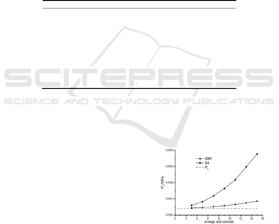
The numerical results of the average size of the
seven units are compared in plan 6 - plan 12 for mesh
convergence analysis, the comparison between the
numerical calculation results of some unit types and
the experimental results is shown in Fig. 3.
From Table 2 and Figure 3, it can be seen that for
the S8R unit type, the mesh refinement operation has
little effect on the convergence of the numerical
analysis results, even if the division is very “rough”
mesh, such as plan 12, the error between the
numerical analysis results and the test results is still
less than 1%, the superiority of the S8R in numerical
analysis was proven again.
Figure 3: Comparison of numerical calculation results of
some unit types with experimental results.
Combined with the comparison results of the
universal shell unit S4, the unit average length is
preferred to select the two unit numerical results and
ISWEE 2022 - International Symposium on Water, Ecology and Environment
120
the test result error is less than 1% of the 5mm length
dimension. In the circular toroidal shell, since R>r, it
is more reasonable to evaluate the average size of the
unit with taking r as a reference, so, 5% of the r size
should be prioritized as average unit size for
numerical analysis of circular toroidal shell stability
under external pressure.
3.3.2 Solid Unit Numerical Result Analysis
By comparing plan 13 - plan 17, the results of
numerical analysis using C3D8 and C3D8R were
found to be significantly different from the
experimental results of Fishlowite, especially the
C3D8, the error was 34.75%. The numerical analysis
results using the C3D20, the C3D20R, and the C3D8I
are highly consistent with the results of using the shell
unit, the error with the results of Fishlowite
experimental was less than 1%.
Due to the huge computational workload of the
C3D20, the relative computational efficiency is much
lower than that of the C3D20R and the C3D8I,
comparison of errors with the results of Fishlowite
test, obviously, the C3D20R is the first choice for the
numerical analysis of the stability of the circular
toroidal shell under external pressure.
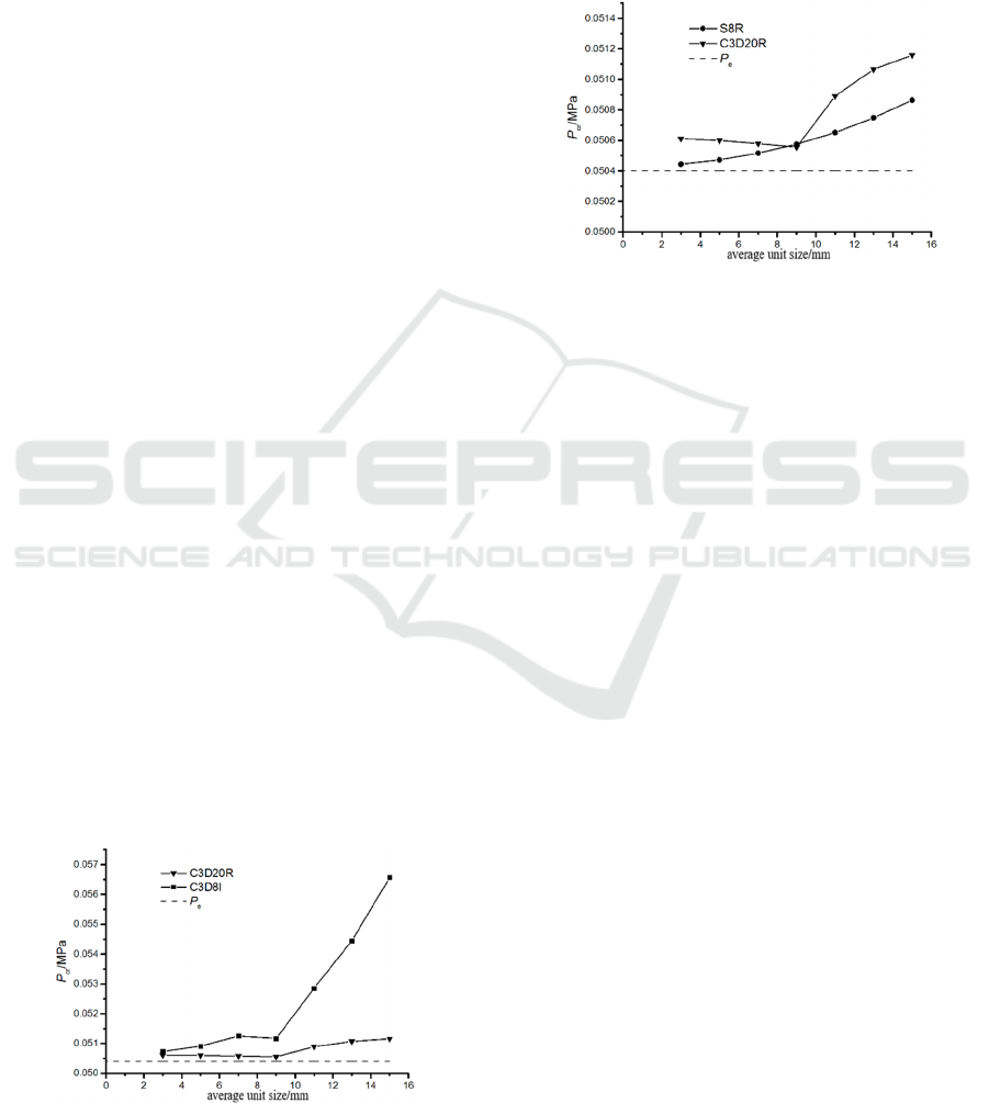
By comparing plan 16-plan 23, it can be found that
for the C3D20R, with mesh refinement,numerical
analysis and test results vary from large to small, then
from small to large ,the error is the smallest when the
average mesh size is 9mm, which is 0.31%.
However, considering the average size of 5mm,
the calculation error of the C3D8I unit is close to 1%
and the calculation efficiency of the unit is higher
[18]
.
It should be mentioned that in the case of a small unit
distortion (C3D8I unit is sensitive to distortion), a
C3D8I (0.05r) unit with an average size of 5mm
should be considered first; otherwise the C3D20R
unit with an average size of 9mm (0.09r) should be
chosen. The comparison between the numerical
analysis results and the test results of C3D20R unit
and C3D8I unit is shown in Fig. 4.
Figure 4: Comparison of numerical results and test results
of different unit types
.
It is worth noting that in the numerical calculation
of all shell unit types, only the calculation result of
the solid unit C3D8R is smaller than the test result.
It can be seen from Table 2, Table 3 and Figure 5,
for the thin shell type to circular toroidal shell (such
as this example), the numerical calculation accuracy
and efficiency of the shell unit are higher than the
solid unit.
Figure 5: Comparison of numerical results and test results
of shell elements and solid units.
It can find out that the error between numerical
results and experimental results was within 1% (In
addition to plan 13, 14) the results are highly
consistent by synthesizing the last two columns of
Tables 2 and 3(comparison of experimental results,
Jordan formula results with numerical results) ,the
error between the calculated value of the Jordan
formula and the experimental result is 9% (Table 1),
and the Jordan formula results are more conservative
than the numerical results, it can be seen that the
Jordan formula predicts the buckling load of the
circular toroidal shell more easily, but numerical
analysis methods are more accurate.
4 EFFECT OF PARAMETER t/r
ON STABILITY OF CIRCULAR
TOROIDAL SHELL UNDER
EXTERNAL PRESSURE
The thickness of the circular toroidal shell has a great
correlation with the buckling behavior of the shell, the
theoretical formula and numerical solution of the
buckling load of thin shell are discussed before in this
paper, and the stability analysis of thick shell circular
toroidal shell is carried out here. Its parameters are as
follows:
R=60mm, r=24mm, t=2 mm, E=2500MPa, ν=0.4,
among them , r/t=12 belongs to the thick shell
category. The results of comparing Jordan formula
are shown in Table 4.
Stability of Circular Toroidal Shell Subjected to Uniform External Pressure
121

Compared with the numerical calculation results,
the numerical calculation result of S8R unit type has
the smallest difference with Jordan formula results,
for the circular toroidal shells of the given thick shell
type, the buckling load P
cr
should be 0.88973MPa.
Comparing the numerical results of plan 1 with plan
2-5, the errors are 1.460%, 1.389%, 1.268% and
1.263% respectively. Although the error is small, it
can still be proved that even for thick-shell type
circular toroidal shells, the S8R is still suitable as a
unit type for establishing a circular toroidal shell
numerical solution under external pressure.
Table 4 solid unit plan and numerical analysis results
Plan Average size of units Unit type
P
c
(MPa)
P
0a
(MPa) (
P
c
-
P
0a
)/
P
0a
1 1.2mm(0.05
r
) S8R 0.88973 0.803688 10.71%
2 1.2mm(0.05
r
) C3D8I(2layers) 0.90272 0.803688 12.32%
3 1.2mm(0.05
r
) C3D8I(2layers) 0.90209 0.803688 12.24%
4 2.2mm(0.09
r
) C3D20R(2layers) 0.90101 0.803688 12.11%
5 2.2mm(0.09
r
) C3D20R(2layers) 0.90097 0.803688 12.10%
5 CONCLUSIONS
Comprehensive consideration of the calculation
accuracy and efficiency of numerical simulation, it is
recommended to use the S8R unit type with four-
point constraint and unit average size of 0.05r to
establish the shell unit numerical plan of the circular
toroidal shell under external pressure.
Comparing shell unit and solid unit, it is
recommended to choose a shell type in the circular
toroidal shell in the thin shell category to establish a
numerical model; for the thick shell category and the
circular toroidal shell near the boundary line
[20]
between the thin shell and the thick shell (r=20t), the
shell unit and the solid unit numerical model can be
simultaneously established, and the unit type with
smaller result is selected.
Compared with the Jordan formula, the numerical
results differ from the experimental results by a small
difference; Jordan formula can be used to predict
buckling load when t/r < 1/14, this is more efficient;
when t/r ≥ 1/14, the numerical calculation method
should be used to predict the buckling load.
ACKNOWLEDGEMENTS
This work was supported by the Natural Science
Foundation of Jiangsu Province [grant number
BK20211343]
.
REFERENCES
Flügge W., and Sobel, L. H., Locheed Missiles and Space
Company Report 6-75-65-12 (Mar.1965).
Sobel L. H., and Flügge, W., AIAA, S (1967), 425-431.
Fishlowitz, E.G., NSRDC Rept.3338, April(1972), Dept.of
the Navy, Naval Research and Development Center,
Washington,D.C.
Jordan, P.F. Buckling of circular toroidal shells under
hydrostatic pressure. AIAA Journal, 1973, 11(10):
1439-1441.
Du Q H, Cui W C, Zhang B. Buckling characteristics of a
circular toroidal shell with stiffened ribs. Ocean
Engineering, 2015, 108:325-335.
Du Q H, Cui W C, Wan Z Q. Nonlinear Finite Element
Analysis of acircular toroidal shell with Ring-Stiffened
Ribs Asme International Conference on Ocean.
American Society of Mechanical Engineers, 2010.
Galletly G D, Blachut J. Stability of Complete Circular and
Non-Circularcircular toroidal shells. Proceedings of the
Institution of Mechanical Engineers, Part C: Journal of
Mechanical Engineering Science, 1995, 209(4):245-
255.
Jordan, P.F. Analytical and experimental investigation of
pressurised circular toroidal shells. NASA CR-261,
1965.
Jordan, P.F. Stiffness of thin pressurised shells of revolution.
Am. Inst. Aeronaut. Astronaut.1965,3,899-906.
Jordan, P. F. and Shelley, P. E. Stabilisation of unstable two-
point boundary value problems. Am. Inst. Aeronaut.
Astronaut.1966,4.923-924.
K.Hibbitt, S.Inc, ABAQUS-Theory and Standard User’s
Manual Version 6.3, USA,2006.
Zhang J, Gao J, Wang W. Investigation on mechanical
properties of deep sea spherical pressure shell. China
ship building, 2015,56(04):129-140.
Blachut,J., Jaiswal O R. On buckling of circular toroidal
shells under external pressure. Computers & Structures,
2000, 77(3):233-251.
TOMAS A, TOVAR J P. The influence of initial geometric
imperfections on the buckling load of single and double
curvature concrete shells. Computers & Structures,
2012, 96(97):3445.
China Classification Society Diving System and
Submersible Classification and Construction
Specifications. BeiJing: People's communications
publishing house, 1996.
ISWEE 2022 - International Symposium on Water, Ecology and Environment
122
