
Reliability Analysis of LCCC Leaded Solder Joints Under Thermal
Cyclic Loading Conditions
Zhang Yukun, Zhang Chun and Xu Weiling
Beijing Institute of Space Mechanics&Electricity, Beijing, China
Keywords: LCCC Package, Finite Element, Thermal Fatigue Life.
Abstract: In this paper, a finite element analysis model of the stress-strain of the solder joints of LCCC package
devices is established to analyze the stress-strain of the solder joints of LCCC devices under temperature
cyclic loading, and the effect of the substrate material on the thermal fatigue life of the solder joints is
analyzed. The results show that the use of Al
2
O
3
, the same material as the LCCC package, as the substrate
can effectively improve the thermal fatigue life of the solder joints under thermal cyclic loading conditions.
In practical applications, the Al
2
O
3
material transfer method can be used to improve the thermal fatigue life
of LCCC package devices.
1 INTRODUCTION
LCCC (Leadless Ceramic Chip Carrier) devices are
widely used in electronic products in various
industries due to their small size, high pin density,
high speed and high frequency. However, due to the
large difference in thermal expansion coefficients
between the packaging material and the FR4-based
PCB, the cyclic stress and strain on the solder joints
between the components and the PCB will be caused
under the action of high and low temperature cycles,
and when the thermal cyclic stress reaches a certain
number of times, it will cause the solder joints to
crack, which are used for mechanical support and
electrical connection in the electronic packaging
structure, and the cracked solder joints will
eventually lead to component failure. Therefore, it is
important to study the stress-strain law of LCCC
package solder joints under thermal cyclic loading.
This research has been carried out by scholars. The
stress-strain distribution of plastic ball grid array
(PBGA) devices under thermal cyclic loading
conditions has been investigated, and laminated
solder joints have been used to improve the thermal
fatigue life of solder joints under thermal cyclic
loading conditions(Wei et al., 2013). Some scholars
have analyzed the variation of thermal fatigue life
with solder joint materials by applying thermal
cyclic loads to solder joints of different materials by
experimental methods(Gao et al., 2018; Gao et al.,
2018),. Some scholars have studied the thermal
fatigue life of LCCC package devices under -30℃
~50 ℃ temperature cycling conditions based on
finite element simulation and engineering algorithm
respectively(Hou et al., 2014). The influence of filler
adhesive parameters on the reliability of lead-free
solder joints based on the Anand intrinsic model was
investigated(Zhang et al., 2000). The results showed
that the elastic modulus of the filler adhesive has no
significant effect on the thermal fatigue life of the
solder joints, while the coefficient of linear
expansion of the material has a significant effect on
the thermal fatigue life of the solder joints.
The above literature does not discuss the
influence of solder joint height and substrate
material on the reliability of LCCC packages under
temperature cyclic loading conditions. In this paper,
the stress-strain analysis of LCCC devices based on
ANSYS finite element analysis software is used to
study the effect of change in solder joint height and
substrate material on the thermal fatigue life of
LCCC devices to further improve the reliability of
the solder joints of LCCC devices.
372
Yukun, Z., Chun, Z. and Weiling, X.
Reliability Analysis of LCCC Leaded Solder Joints Under Thermal Cyclic Loading Conditions.
DOI: 10.5220/0011933300003612
In Proceedings of the 3rd International Symposium on Automation, Information and Computing (ISAIC 2022), pages 372-376
ISBN: 978-989-758-622-4; ISSN: 2975-9463
Copyright
c
2023 by SCITEPRESS – Science and Technology Publications, Lda. Under CC license (CC BY-NC-ND 4.0)

2 LCCC PACKAGE THERMAL
CYCLING STRESS-STRAIN
FINITE ELEMENT ANALYSIS
2.1 Finite Element Model of LCCC
Package Solder Joints
The object of analysis in this paper is the LCCC
(leadless Ceramic Chip Carrier) package, the model
entity is derived from the CMOS image sensor
produced by BAE, the device body size is 40mm ×
50mm × 4.5mm, a total of 194 pads, pad center
spacing of 0.8mm, the bottom pad size is 1.4 mm ×
0.38mm. To reduce the impact of PCB edge stress
strain on the solder joint, the PCB size is taken to be
two times the size of the device package, the PCB
size is 80mm × 100mm × 2mm. The selected solder
joint material is Sn63Pb37 solder paste.
Considering the actual situation of the printed
circuit board on the copper wire filling glue and
other materials to establish a finite element model is
very difficult, in order to improve the efficiency of
the analysis, shorten the analysis time, the model
will do some simplification process. In this paper,
the LCCC geometric model design assumptions: 1)
ignore the printed board manufacturing process used
in the filling glue and other materials and the
influence of metal compounds between the solder
joints; 2) all parts of the model are ideally
connected, ignoring defects such as voids in the
solder joints; 3) when the ambient temperature
changes, the overall temperature of the package are
equal, there is no temperature gradient; 4) the initial
temperature of 25 ℃, the initial stress inside the
package is 0.
2.2 Material Ontology Equations and
Parameters
Due to the more obvious inelastic stress-strain
characteristics of lead-tin materials, in the finite
element analysis of the solder joints using Anand
viscoplastic instantonal equation to describe its
mechanical behaviour. Sn63Pb37 solder paste
material performance parameters are shown in Table
1. The parameters of the Anand model for Sn63Pb37
solder paste are shown in Table 2.
Table 1: Material properties of
Sn63Pb37 solder paste
.
Temp.(℃)
Elastic modulu(GPa) Poisson
-55 47.97 0.352
-35 46.89 0.354
-15 45.79 0.357
5 44.38 0.360
20 43.25 0.363
50 41.33 0.365
75 39.45 0.37
100 36.85 0.77
Table 2: Anand model material parameters for Sn63Pb37 solder paste.
S
0
(MPa)
Q /R(K
-1
)
A(sec
-1
) ξ m h
0
(MPa)
𝑠
̂
(MPa)
n
a
12.41 9400 4.0e6 1.5 0.303 1378.95 13.79 0.07 1.3
The PCB board for each anisotropic linear
elastic material, ceramic package, copper solder tray
and the rest of the parts are each homogeneous linear
elastic material. Material parameters are shown in
Table 3.
Table 3: The remaining material properties.
Materials Elastic
modulu
(GPa)
Poisson
ratio
CTE
(10
-6
1/K)
Al
2
O
3
310 0.22 7
FR-4PCB(x,
y
)35 0.12 20.6
FR-4PCB(z) 14 0.12 68.3
Solder pads 110 0.34 17
Reliability Analysis of LCCC Leaded Solder Joints Under Thermal Cyclic Loading Conditions
373

2.3 Modeling and Boundary
Conditions
The model is simplified to a quarter structure
considering symmetry, Visco107 viscoplastic solid
cells are used for the weld joint cell type, and
Solid45 solid cells are used for all other structures.
Establish the finite element analysis model and mesh
division as shown in Fig. 1 and Fig. 2. Symmetry
constraints are applied to the x-z and y-z symmetry
planes of the model, and full constraints are applied
to the symmetry center nodes on the bottom surface
of the PCB.
Figure 1: LCCC finite element analysis model.
Figure 2: Model mesh division.
2.4 Thermal Cycle Loading Condition
The thermal cycling load is applied with reference to
a standard, the initial temperature is set at room
temperature 25°C, the upper temperature 100°C, the
lower temperature -55°C, the high and low
temperature limits are insulated for 900s, the
temperature change rate does not exceed 0.17°C/s,
each cycle 3600s. The loading curve is shown in
Figure 3. The finite element analysis was calculated
using 4 temperature cycle cycles.
0246810121416
-60
-40
-20
0
20
40
60
80
100
120
temp. (
o
C)
time (10
3
s)
temp.
Figure 3: Temperature cycling condition.
2.5 Stress-Strain Finite Element
Analysis Results
After four thermal cycles, the equivalent plastic
strain distribution in the interior of the solder joint at
the end of the fourth week of holding for Sn63Pb37
solder joints is shown in Figure 4.
Figure 4: Equivalent plastic strain distribution
The figure shows that the maximum equivalent force
and strain of the device are located at the sharp corners.
Under thermal cycling loading conditions, the solder joints
at the sharp corners of the device are critical solder joints.
The critical solder joint reaches the maximum equivalent
plastic strain at the end of the high temperature holding
period of 0.05389. The maximum strain inside a single
solder joint is located at the intersection of the bottom and
side pads of the device.
The stress-strain results of the critical weld joint were
extracted and the stress-strain hysteresis curve was plotted
as shown in Figure 5. It can be seen that the curve is
gradually converging to the hysteresis loop shape, and the
fourth cycle hysteresis loop is selected to obtain the plastic
strain range of the critical weld joint within one
temperature cycle is
∆ε = 0.0216
.
ISAIC 2022 - International Symposium on Automation, Information and Computing
374
0123456
0
10
20
30
40
50
60
70
σ(MPa)
ε(10
−2
)
Figure 5: Stress-strain curve.
3 INFLUENCE OF SUBSTRATE
MATERIAL ON THE
THERMAL FATIGUE LIFE OF
LCCC SOLDER JOINTS
3.1 Thermal Fatigue Life Prediction by
LCCC Model
Critical weld joint thermal fatigue life calculation using
Engel-maier modified Coffin-Mason equation for:
𝑁
∆
(1)
c 0.442 6 10
𝑇
1.7410
ln (1𝑓
(2)
∆γ
√
3
∆ε (3)
N
is average thermal fatigue life, ∆γ is equivalent
shear strain range; ε
is fatigue toughness coefficient
of 0.325,
𝑓
is cycling frequency of 24 weeks/day,
∆ε is equivalent plastic strain range.
The above parameters are substituted into
equation (2) to calculate c = -0.3995, and the above
parameters are substituted into equation (1) to
calculate N
≈635.
3.2 Influence of PCB Substrates on the
Thermal Fatigue Life of Solder
Joints
Considering the large stress-strain caused by the
large difference in thermal expansion coefficient
between the LCCC package material and the FR4-
based PCB, the welding substrate was replaced with
Al
2
O
3
of the same material as the LCCC package,
and the rest of the material parameters were kept
unchanged, and the corresponding finite element
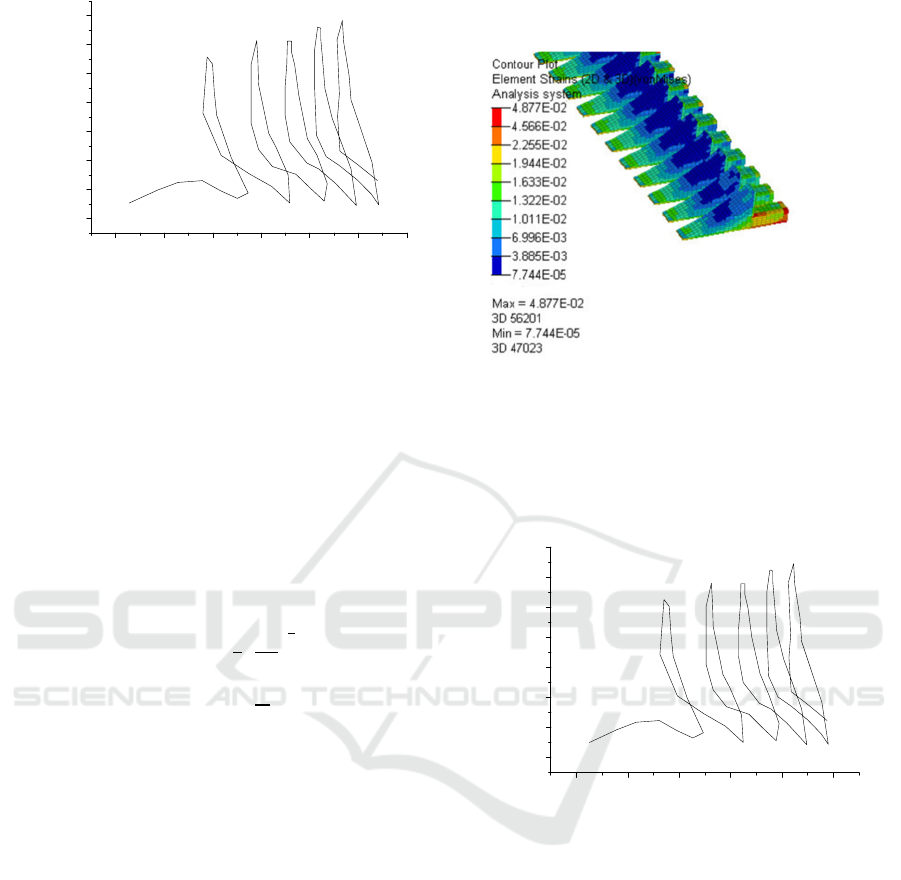
model was established for analysis. From Figure 6
can be obtained from the key solder joints maximum
equivalent plastic strain maximum value of 0.04877.
Figure 6: Maximum equivalent shaping strain of ceramic
substrate.
The stree-strain curve for a solder joint with
Al
2
O
3
as the substrate is shown in
Figure 7. From the figure it
can be seen that the strain range of the solder joint within
one temperature cycle is
∆ε = 0.0192
.
012345
0
10
20
30
40
50
60
70
σ
(MPa)
ε (10
−2
)
Figure 7: Stress-strain curve.
Bring the parameters into equation (1) and the
thermal fatigue life N
≈ 852 was calculated for the
LCCC encapsulated device with Al
2
O
3
as the
substrate, which is better than the thermal fatigue
life of the LCCC encapsulated device with FR4 as
the substrate.
4 CONCLUSIONS
The results of the analysis show that the highest
stress strain is applied to the sharp corners of the
LCCC package, where the solder joints are the first
to fail.
Compared to FR4 substrate printed boards,
using Al
2
O
3
, which is the same material as LCCC
Reliability Analysis of LCCC Leaded Solder Joints Under Thermal Cyclic Loading Conditions
375

package, as the substrate can effectively improve the
thermal fatigue life of solder joints under thermal
cyclic loading conditions.
In the actual application of LCCC package
devices, the devices can be soldered to the Al
2
O
3
material adapter first, and then the adapter is
soldered to the printed circuit board with a highly
reliable connection such as through-hole soldering to
improve the thermal fatigue life of LCCC package
devices.
REFERENCES
Gao, L., Li, C., and Wan, P., (2017). A Superior
Interfacial Reliability of Fe-Ni UBM During High
Temperature Storage.Journal of Materials
Science:Materials in Electronics, 28(12):8537-8545
Gao, L., LIU, Z.and LI, C.,(2017).
Failure Mechanisms of
SAC/Fe-Ni solder Joints During Thermal
Cycling .Journal of Eletronic Materials, 46
(8):5338-5348.
Hou, C., Tong ,J. and Rong, K. , (2014).
Thermo-fatigue
life study on LCCC electronic packaging
structure.
structure & environment engineering, 41
(3):51-57.
Lall, P., Islam, M.N. , and Singh, N. (2004). Model for
BGA and CSP reliability in automotive under hood
applications. IEEE Transactions on Components &
Packaging Technologies, 27(3):585-593.
Wei, H., Huang, C., and Liang, Y. , (2013) .Reliability
analysis of plastic ball grid array double-bump lead-
free solder joint under thermal cycle. transactions of
the china welding institution, 34(10):91-95.
Zhang, X ., and Lee, S.W. , (2000) .Thermal fatigue
analysis solder joints. Journal of Electronic
Packaging, 122(3):200-206.
ISAIC 2022 - International Symposium on Automation, Information and Computing
376
