
Control Techniques Applied to Two Degrees of Freedom Planar
Robotic Arm
J G Maradey-Lazaro
1
a
, A D Rincon-Quintero
2,3
b
, Kevin Sebastián Caceres-Mojica
1
c
, C L
Sandoval-Rodriguez
2,3
d
and O Lengerke
1
e
1
Universidad Autónoma de Bucaramanga UNAB, Bucaramanga Santander 680003, Colombia
2
Unidades Tecnológicas de Santander UTS, Bucaramanga Santander 680005, Colombia
3
University of the Basque Country UPV/EHU, Bizkaia 48013, Spain
Keywords: Control design, control Techniques applied, degrees of freedom, mechatronics systems, robotic arm.
Abstract: The automation of production processes using robotic manipulators seems to be one of the most advanced
technological areas in the last decade, as it provides the possibility of manipulating objects through a versatile
and automatic configuration of manufacturing systems. This type of robot has several uses which can make
the work much easier and safer, offering precision and quality to the development of designated activities in
the world of automation. To obtain this goal, effective control techniques offer a practical alternative to
analyze the behavior of the mechatronics systems considering the natural dynamic of the system and to select
the best for each application, respectively. This article aims to design a robot with two degrees of freedom for
which the dynamic model was obtained, in addition to performing the control design that ensures the stability
of the system, in which the position is measured to obtain the error difference between the desired value and
the actual value.
1 INTRODUCTION
In recent years, it is very common to find in the
automation and control industry, systems or
mechanisms that are useful for performing tasks
or activities involving planar-type robots. An
indicator of the effectiveness of robotic in
improving manufacturing processes is the efforts
made in automatization, industrial and robotic
areas (Kouritem et al., 2022)(Rincon-Quintero,
Sandoval-Rodríguez, et al., 2022).
Considering competitivity as a key factor to
remain in the market, industrial companies are
working to establish a balance between human
labor and the use of robots, in addition to tools
for interaction and collaboration that bring
efficiency to the work being faster, more precise,
a
https://orcid.org/0000-0003-2319-1965
b
https://orcid.org/0000-0002-4479-5613
c
https://orcid.org/0000-0002-7863-915X
d
https://orcid.org/0000-0001-8584-0137
e
https://orcid.org/0000-0001-9360-7319
flexible, in a way that significantly reduces the
cost of production (Xu et al., 2022)(Mendoza-
Calderón et al., 2022).
While it is true, it is not possible to modify
100% of the work performed by a human being,
the specific robotic arm can be extremely useful
for the tasks of assembly and movement of parts
or raw material.
It is important to mention that the position
and orientation of the final effector of the robotic
arm must be considered for the robotic arm to
perform a specific task, which means that a
previous configuration must be taken concerning
an initial reference frame. In addition, a speed
and acceleration analysis are necessary to
perform uniform motion control in the robotic
system (Kayastha et al., 2022)(Rincon-Quintero,
Maradey-Lazaro, J., Rincon-Quintero, A., Caceres-Mojica, K., Sandoval-Rodriguez, C. and Lengerke, O.
Control Techniques Applied to Two Degrees of Freedom Planar Robotic Arm.
DOI: 10.5220/0011954000003612
In Proceedings of the 3rd International Symposium on Automation, Information and Computing (ISAIC 2022), pages 495-503
ISBN: 978-989-758-622-4; ISSN: 2975-9463
Copyright
c
2023 by SCITEPRESS – Science and Technology Publications, Lda. Under CC license (CC BY-NC-ND 4.0)
495
Del Portillo-Valdés, Meneses-Jácome, Ascanio-
Villabona, et al., 2021).
Based on this information, a series of
advanced control strategies are proposed, to
adapt the most efficient and optimal technique,
thus obtaining a better version of a two-degree
planar robotic arm of freedom. Therefore, three
control strategies have been studied in the next
sections: PID, LQR (i.e Linear-Quadratic
regulator) control and observer for pole location,
and LQG (i.e Linear—Quadratic-Gaussian)
control and filter of Kalman using values such as
IAE (i.e., Integral absolute Error), ITAE (i.e.,
Integral Time Absolute Error), ISE( i.e., Integral
Square Error), and ITSE ( i.e., Integral Time
Square Error).
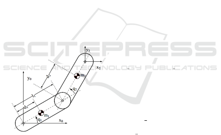
2 MATHEMATICAL MODEL
This modeling presents the description of the
dynamics of a two-degrees of freedom planar robot,
which exposes its main characteristics in Figure 1 (Ni
et al., 2022).
Figure 1 : The two-degree flat robotic arm of freedom (Ni et
al., 2022).
Below are the coordinates and speeds of the centers of
mass of element 1. It is important to mention that C1,
S1, C12 and S12 correspond to Cos(q1), Sin(q1),
Cos(q1+q2) and Sin(q1+q2) respectively.
(1)
(2)
(3)
(4)
And using the above equations you can set the
following:
(5)
Below are the coordinates and speeds of the mass
centers of element 2.
(6)
(7)
(8)
(9)
And using the above equations you can set the
following:
(10)
Below are the equations corresponding to the
kinetic energy and potential energy of the system
respectively.
(11)
(12)
Lagrangian is now applied to the above equations
by getting the following:
(13)
Finally, the final equations corresponding to:
(14)
ISAIC 2022 - International Symposium on Automation, Information and Computing
496
(15)
2.1 State Space System Model
Based on the above equations it is possible to
formulate the two degrees of freedom planar arm
system in state space, to apply a complete and robust
multivariate control to the model (Rincon-Quintero,
Portillo-Valdés, et al., 2021). Table 1 shows the
System States of 2 DOF Planar Robotic Arm and
Table 2 report the inputs to the model. Similarly, in the
Table 3 the numerical parameters taken to run the
model are shown.
(16)
(17)
Table 1 : System States.
2DOF Planar Robotic Arm States
States
Nomenclature
Variable
Link position 1
Link position 2
Link speed 1
Link speed 2
Table 2. System Inputs
2DOF Planar Robotic Arm System Inputs
Inputs
Nomenclature
Variable
Link Torque 1
Link Torque 2
In this way, the equations of the system in state
space are the following:
; A=
(18)
C
; D
(19)
Table 3 : Parameters
2DOF Planar Robotic Arm Parameters
Parameters
Value
Unit
Link mass 1
0.345
Link mass 2
0.106
Distance from link 1
to the center of mass
0.25
Distance from link 2
to the center of mass
0.11
Gravity constant
9.81
Link length 1
0.3
Subsequently, we proceed to compare the linear
system of the mathematical model with the nonlinear
system to establish a path that allows the multivariate
control mentioned above.
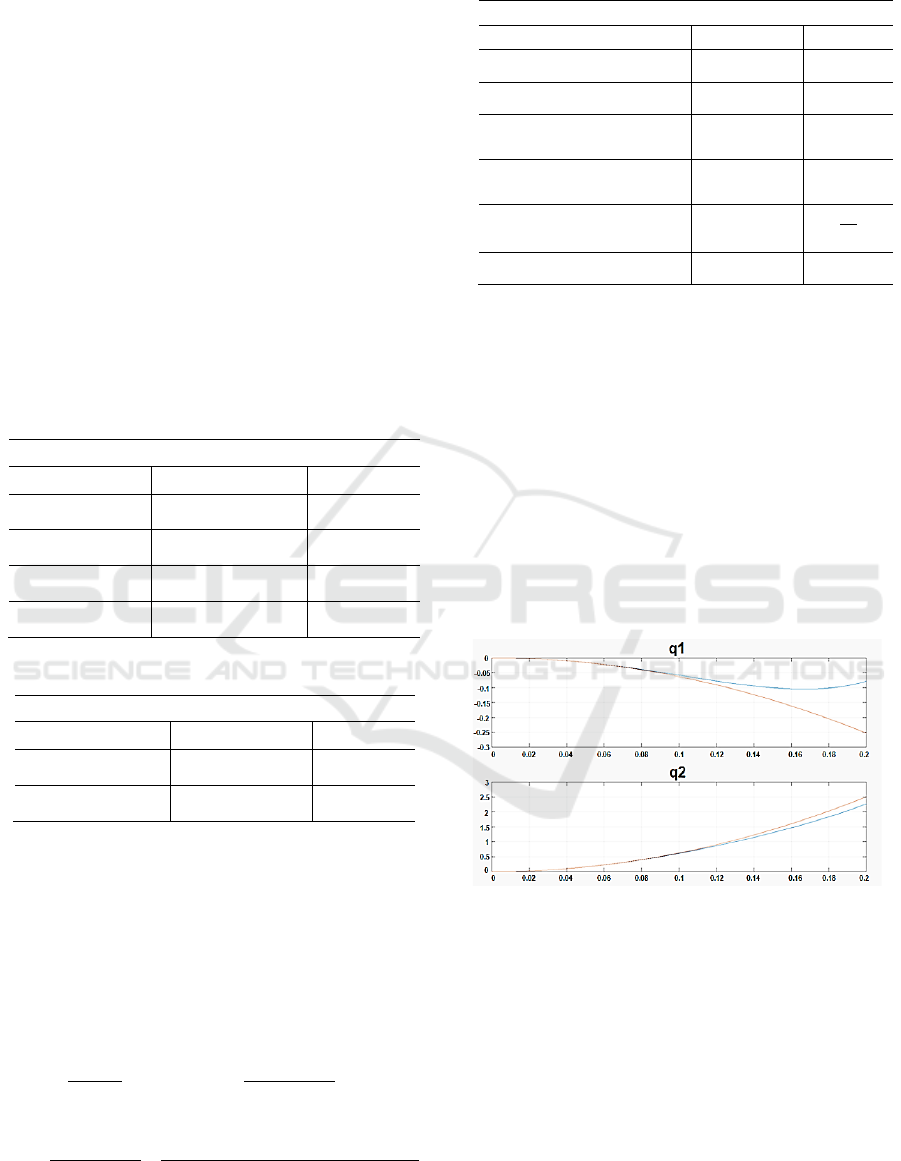
Figure 2 shows the basic system states
corresponding to the position of link 1 and link 2 of
the two degrees of freedom planar robotic arm. From
there it can be inferred that the position of link 1 has
similarity in both systems (linear and nonlinear) up to
approximately 0.1 degrees and that the position of link
2 to point 0.12 degrees. This allows us to conclude that
the proposed linear system behaves sufficiently like
the nonlinear system to apply multivariate control to
the model in question.
Figure 2 : Linear model and non-linear model of the
system.
2.2 Control Technique PID
As a first step, a PID control technique is applied
where it is possible to analyze the variables of inputs
or variables to be controlled (Satya Durga Manohar
Sahu et al., 2022)(Rincon-Quintero, Del Portillo-
Valdés, Meneses-Jácome, Sandoval-Rodríguez, et al.,
2021). In this case the torques of links 1 and 2 of the
planar robotic arm of two degrees of freedom. As can
be seen in Figure 3 for the first torque you have a
controller that stabilizes the system in 0.839 seconds,
with a lifting time of 0.463 seconds and without any
Control Techniques Applied to Two Degrees of Freedom Planar Robotic Arm
497
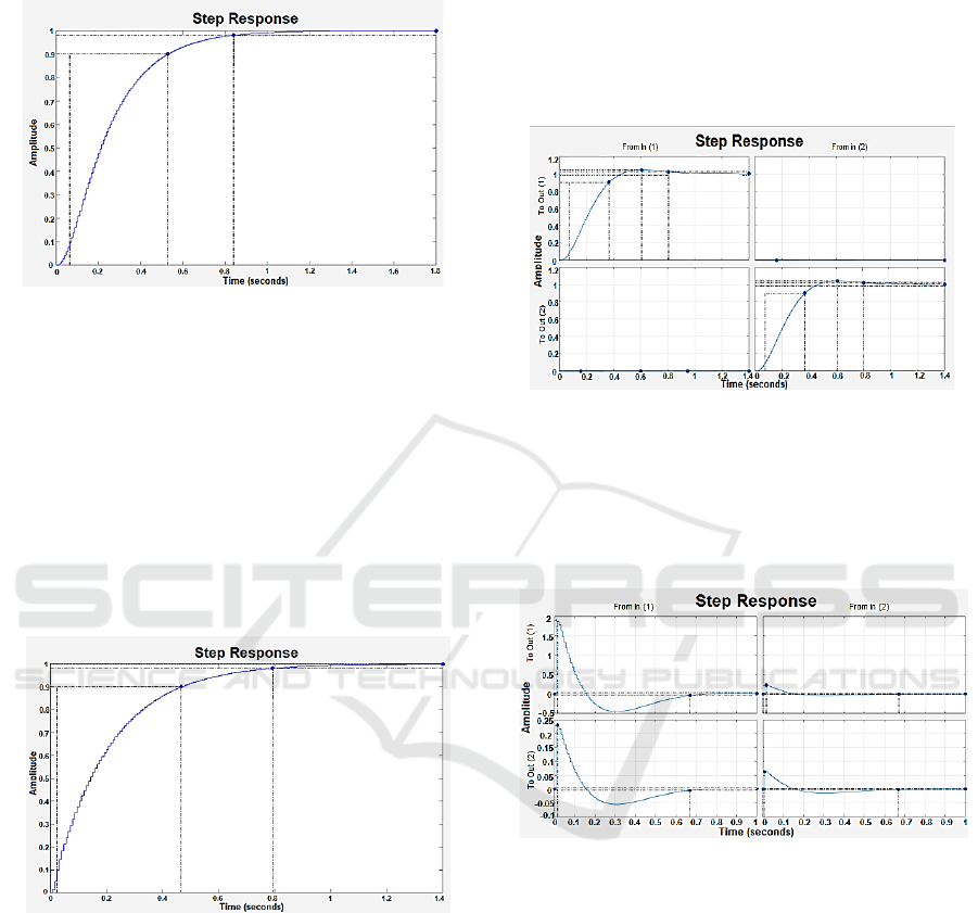
overpasses. Despite not being a very advanced control
technique the results that were obtained with this first
controller were very satisfactory.
Figure 3 : Torque one closed-loop response with PID.
As a second measure, a PID-type controller is also
designed for link 2 torque of the planar robotic arm.
Through Figure 4 it can be observed that this torque
was controlled in approximately 0.792 seconds with a
lifting time of 0.443 seconds and without any
overpasses. These data obtained allow analysis that
although both controllers were designed separately.
They were of a PID nature, at the time of unifying
them behave according to the results observed in the
graphs, because they have very similar parameters,
such as the establishment and lifting times of the
system.
Figure 4 : Torque two closed-loop response with PID.
2.3 LQR Control Technique and
Observer by Pole Location
This first advanced control technique called LQR is
accompanied by an observer by pole location, this one
is commonly used to estimate system states (Misra et
al., 2020)(Rincon-Quintero, Del Portillo-Valdés, et
al., 2022). It is important to mention that this
controller allows to perform multivariate analysis, that
is, to the differential of the PID control technique, this
controller allows to influence both variables over time.
In Figure 5 can be observed for the first variable,
i.e., link 1 torque, a signal set time of 0.806 seconds,
and a lift time of 0.289 seconds. For link 2 torque, an
establishment time of 0.802 seconds and a lifting time
of 0.291 seconds can be seen. In addition, it is possible
to claim that both variables to be controlled showed an
overpass of 4.21% and 3.97%. The data obtained from
both signals were very similar.
Figure 5 : The closed-loop system with LQR and pole
location observer.
Based on Figure 6 you can observe the control actions
of the variables affected by the control carried out
above. In any case, no signal presents behavior that
can negatively influence the behavior of the controlled
system.
Figure 6 : Control action of the closed-loop system with
LQR and observer by pole location.
2.4 Control Technique with Kalman
Filter
Better known as an LQG control technique, this
controller allows the union of optimal LQR control
with a Kalman filter (Narayan et al., 2020)(Rybus et
al., 2022). The Kalman filter is a set of mathematical
equations that provides an efficient computational
(recursive) solution of the least-squares method.
The filter is very powerful in several aspects: it
supports estimations of past, present, and even future
states, and it can do so even when the precise nature
of the modeled system is unknown (Sanchez et al.,
2022). This tool is useful for identifying the non-
ISAIC 2022 - International Symposium on Automation, Information and Computing
498
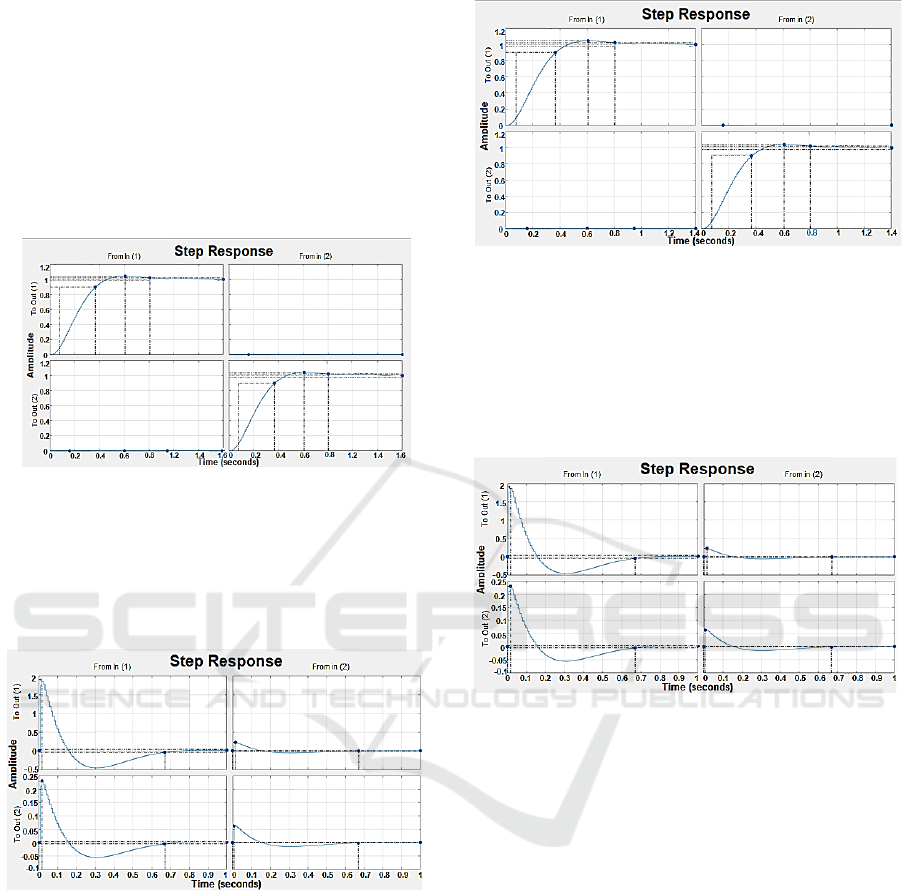
measurable state of a linear system, in this case, the
two degrees of freedom planar robotic arm. Figure 7
illustrates the closed-loop system of the model with
the controlled variables, i.e., the torques of the links.
The first torque shows control with a set time of
0.812 seconds and a lifting time of 0.292 seconds.
Similarly, an overpass of 4.25% can be differentiated.
For link 2 it is observed that at 0.812 seconds torque 2
manages to stabilize, previously having a lifting time
of 0.294 seconds and an overpass of 4.21%.
Figure 7 : The closed-loop system with LQG.
As in the previous section, Figure 8 shows the control
action of each of the variables caused by the controls
applied using the LQG technique. However, these
signals do not affect either the working range or the
behavior of the controller.
Figure 8 : Control action of the closed-loop system with
LQG.
“Two-degree-of-freedom (2DOF) PID controller" is
a 2DOF controller whose serial compensator is a PID
element and whose feedforward compensator is a PD
element (Abhishek & Kumar Dalla, 2022).
Through Figure 9 you can see a slight overpass in
both variables to be controlled of 0.608%, an
establishment time of 0.812 seconds, and a lifting
time of 0.291 and 0.292 seconds. The great advantage
of unifying these techniques is that the behavior of the
variables to be controlled against a control action is
almost the same.
Figure 9 : The closed-loop system with two degrees of
freedom control.
As shows in Figure 10, for the control action caused
in the system, it possible to note the influence all
variables of the model, however, in two of them the
negative overstep is greater and this is mainly due to
the robust and forced nature of the controller over the
variables in question.
Figure 10 : Control action with two degrees of freedom
control.
2.5 DOF Control Technique
For the latest applied control technique, we then have
unified control of an LQR along with a Kalman filter
under the 1 degree of freedom mode. The 1 DOF
control technique suffers from the limitation that
there exists a compromise between response and loop
goal performances (Fortunato et al., 2022). It can be
seen in Figure 11 that the behavior, in this case, is not
the best due to a considerable overfits of 69.3% in
torque 1 and another even larger overstep of 92.6% in
the torque of link 2.
As for the establishment times in both cases, it was
0.716 and 0.403 seconds. And the rise time was
0.0607 and 0.0184 seconds. While it is true the times
in which both torques stabilize are very good,
however, the oversteps negatively affect the behavior
of the signals in question.
Control Techniques Applied to Two Degrees of Freedom Planar Robotic Arm
499
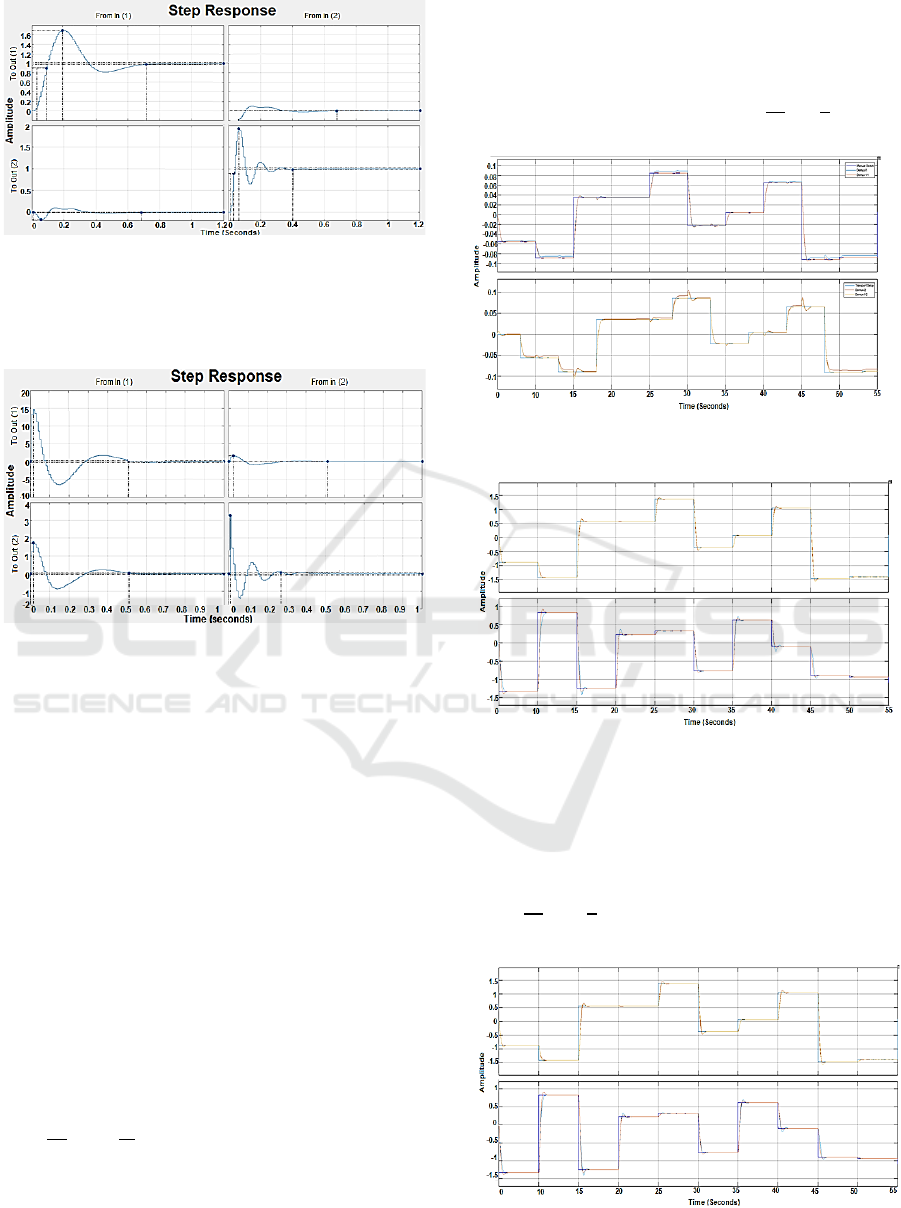
Figure 11 : Closed-loop system with one degree of freedom
control.
And finally, you can see a behavior very similar to the
control signal in the control action of each of the
variables in Figure 12.
Figure 12 : Control action with control of a degree of
freedom.
3 RESULTS AND CONCLUSIONS
For better compression of the digital control
techniques applied above, this section shows the
system behavior under the applied control technique,
given a range of operations and several set points.
Similarly, the nonlinear model of the system is shown
in the same graph to have a closer perception of what
these control strategies applied to the robot would be.
In the first comparison plot corresponding to
Figure 13, it can observe the variables to be
controlled, i.e., the torques of the robot links, under
the PID control technique. For ranges farther from
zero, you can see that the nonlinear model is not able
to reach its set point, and when the set point of one
variable changes, the control signal of the other
variable is affected as it is a unified multivariate
control. It is important to mention that the operating
range for this control technique ranges
from
until
.
In this second comparison plot (i.e Figure 14)
corresponding to the LQR control technique and the
observer by pole location you can see that always the
variable in the process reaches its set point, however,
the same phenomenon described in the graph above
occurs, where the control signal in one variable is
affected when the set point of the other variable
changes, this is due to the nature of the controller. The
operating range for this case is from
to
.
Figure 13 : Comparison of the non-linear model with PID
control.
Figure 14 : Comparison of the non-linear model with LQR
control and observer by pole location.
Figure 15 corresponds to the LQG control technique,
where you can see that always the variable in process
reaches its set point without problem, there is a
minimum overs fits, and the operating range is
from
to
. Behavior is very similar to the
previous case.
Figure 15 : Comparison of the non-linear model with LQG
control.
ISAIC 2022 - International Symposium on Automation, Information and Computing
500

Also, Figure 16 corresponds to the two-degree unified
control technique of freedom in which optimal
behavior can be observed in which the variable always
reaches its stability. The operating range is from,
to
.
Figure 16 : Comparison of the non-linear model with 2DOF
control
Finally, In Figure 17 the graph corresponding to the
unified control technique is shown using the 1 degree
of freedom mode. Without a doubt, the variable in the
process does not have the best behavior, due to the
high overpasses, however, if the point of stability is
reached in both variables to be controlled.
The operating range is from,
to
.
For the quantitative evaluation, the error is
determined from the IAE, ITAE, ISE, and ITSE values
is shown in Table 4 as a summary. This, calculating
the difference between the feedback signal and the
operating point values, which represent the error
signal, obtained from the following equations (Rahul
et al., 2019).
Figure 17 :Comparison of the non-linear model with the
control of a degree of freedom.
(20)
()
()
()
Table 4 : Error Rates of the Controls applied to the
System.
Error rates of the controllers applied
Control technique
IAE
ITAE
ISE
ITSE
Control PID
0.2
0.3
6.7
6.7
0.0
0.0
0.3
0.2
LQR control and observer
por pole location
0.3
0.4
0.0
0.1
0.3
0.3
0.0
0.0
LQR control and filter de
kalman
0.3
0.4
0.0
0.1
0.3
0.3
0.0
0.0
Control de 2DOF
0.4
0.2
0.2
1.4
0.3
0.2
0.0
1.3
Control de 1DOF
0.5
0.2
0.3
1.3
0.4
0.2
0.3
1.2
To make a deeper analysis in terms of the comparison
of all the control techniques applied in this research
article, a series of performance indices were
implemented for each variable to be controlled (torque
one and torque two).
The first error rate corresponds to the integral of the
absolute value of the IAE error. This index usually
gives longer set-up times and higher oversteps, so it is
considered one of the most sensitive. The second
index used is the integral of time multiplied by the
absolute value of the ITAE error. In this error, the
transient responses that are obtained usually have
small oversteps and well-cushioned oscillations. The
ISE error square integral penalizes large errors and
discriminates between over-caused and sub-wet
responses.
Finally, the ITSE error rate corresponding to the
integral time multiplied by the error square was
obtained. This is characterized mainly by giving little
importance to initial errors, however, if it influences
the errors present after a few seconds of the start of the
system entry.
Based on the comparison of the control techniques
implemented in this article, the graphs provided, and
the ranges of action, it is decided that the best
controllers implemented are the LQG and LQR with
pole location observer, since they have a wide range
of action from.
to
, their error rates are minimal, their
transient responses have short settling times (0.8
seconds) and very minimal overruns (4.2%).
Once again, the usefulness of these advanced
control techniques for this type of robotic system,
which are used with high frequency in the process
Control Techniques Applied to Two Degrees of Freedom Planar Robotic Arm
501

automation industry worldwide, is proven. Due to
their widespread use and the diversity of models and
systems, it is necessary to carry out this type of
research to create solid bases for the progressive
development of assisted manufacturing.
ACKNOWLEDGEMENTS
This work is supported by the research
management of the Universidad Autónoma de
Bucaramanga, where the research project has a grant
to supports Bachelor´s students in mechatronics
engineering.
REFERENCES
Abhishek, K., & Kumar Dalla, V. (2022). Formulation of
kinematics and gait locomotion for Hyper-
Redundant robot. Materials Today: Proceedings, 56,
976–979.
https://doi.org/10.1016/j.matpr.2022.03.110
Fortunato, G. M., Bonatti, A. F., Batoni, E., Macaluso, R.,
Vozzi, G., & De Maria, C. (2022). Motion
compensation system for robotic based in situ
bioprinting to balance patient physiological
movements. Bioprinting, 28(October), e00248.
https://doi.org/10.1016/j.bprint.2022.e00248
Kayastha, S., Katupitiya, J., Pearce, G., & Rao, A. (2022).
Comparative study of post-impact motion control of
a flexible arm space robot. European Journal of
Control, xxxx, 100738.
https://doi.org/10.1016/j.ejcon.2022.100738
Kouritem, S. A., Abouheaf, M. I., Nahas, N., & Hassan, M.
(2022). A multi-objective optimization design of
industrial robot arms. Alexandria Engineering
Journal, 61(12), 12847–12867.
https://doi.org/10.1016/j.aej.2022.06.052
Mendoza-Calderón, K. D., Jaimes, J. A. M., Maradey-
Lazaro, J. G., Rincón-Quintero, A. D., & Cardenas-
Arias, C. G. (2022). Design of an Automatic
Palletizer. Journal of Physics: Conference Series,
2224(1), 0–15. https://doi.org/10.1088/1742-
6596/2224/1/012095
Misra, A., Sharma, A., Singh, G., Kumar, A., & Rastogi, V.
(2020). Design and Development ofa Low-Cost
CNC Alternative SCARA Robotic Arm. Procedia
Computer Science, 171(2019), 2459–2468.
https://doi.org/10.1016/j.procs.2020.04.266
Narayan, J., Mishra, S., Jaiswal, G., & Dwivedy, S. K.
(2020). Novel design and kinematic analysis of a 5-
DOFs robotic arm with three-fingered gripper for
physical therapy. Materials Today: Proceedings, 28,
2121–2132.
https://doi.org/10.1016/j.matpr.2020.04.017
Ni, S., Chen, W., Ju, H., & Chen, T. (2022). Coordinated
trajectory planning of a dual-arm space robot with
multiple avoidance constraints. Acta Astronautica,
195(December 2021), 379–391.
https://doi.org/10.1016/j.actaastro.2022.03.024
Rahul, K., Raheman, H., & Paradkar, V. (2019). Design and
development of a 5R 2DOF parallel robot arm for
handling paper pot seedlings in a vegetable
transplanter. Computers and Electronics in
Agriculture, 166(February), 105014.
https://doi.org/10.1016/j.compag.2019.105014
Rincon-Quintero, A. D., Del Portillo-Valdés, L. A.,
Meneses-Jácome, A., Ascanio-Villabona, J. G.,
Tarazona-Romero, B. E., & Durán-Sarmiento, M. A.
(2021). Performance Evaluation and Effectiveness
of a Solar-Biomass Hybrid Dryer for Drying
Homogeneous of Cocoa Beans Using LabView
Software and Arduino Hardware BT - Recent
Advances in Electrical Engineering, Electronics and
Energy (M. Botto Tobar, H. Cruz, & A. Díaz Cadena
(eds.); pp. 238–252). Springer International
Publishing.
Rincon-Quintero, A. D., Del Portillo-Valdés, L. A.,
Meneses-Jácome, A., Sandoval-Rodríguez, C. L.,
Rondón-Romero, W. L., & Ascanio-Villabona, J. G.
(2021). Trends in Technological Advances in Food
Dehydration, Identifying the Potential Extrapolated
to Cocoa Drying: A Bibliometric Study BT - Recent
Advances in Electrical Engineering, Electronics and
Energy (M. Botto Tobar, H. Cruz, & A. Díaz Cadena
(eds.); pp. 167–180). Springer International
Publishing.
Rincon-Quintero, A. D., Del Portillo-Valdés, L. A.,
Zanabria-Ortigoza, N. D., Sandoval-Rodriguez, C.
L., Maradey-Lázaro, J. G., & Castillo-León, N. Y.
(2022). Exergy analysis and development of flat
plate solar collectors: A Review. IOP Conference
Series: Materials Science and Engineering, 1253(1),
012009. https://doi.org/10.1088/1757-
899x/1253/1/012009
Rincon-Quintero, A. D., Portillo-Valdés, L. A. Del,
Cárdenas-Arias, C. G., Tarazona-Romero, B. E.,
Rondón-Romero, W. L., & Durán-Sarmiento, M. A.
(2021). A bibliometric analysis of the uses of the
cocoa pod shell. IOP Conference Series: Materials
Science and Engineering, 1154(1), 012032.
https://doi.org/10.1088/1757-899x/1154/1/012032
Rincon-Quintero, A. D., Sandoval-Rodríguez, C. L.,
Lengerke-Perez, O., Rueda-Osma, M. F., & Mateus-
Ariza, J. A. (2022). Evaluation and Control of
Psychrometric Variables Present in an Automated
Greenhouse for the Production of Organic Tomato
BT - Recent Advances in Electrical Engineering,
Electronics and Energy (M. Botto-Tobar, H. Cruz, &
A. Díaz Cadena (eds.); pp. 165–180). Springer
International Publishing.
Rybus, T., Wojtunik, M., & Basmadji, F. L. (2022).
Optimal collision-free path planning of a free-
floating space robot using spline-based trajectories.
Acta Astronautica, 190(June 2021), 395–408.
https://doi.org/10.1016/j.actaastro.2021.10.012
Sanchez, M., Cruz-Ortiz, D., Ballesteros, M., Salgado, I., &
ISAIC 2022 - International Symposium on Automation, Information and Computing
502

Chairez, I. (2022). Output feedback robust control
for teleoperated manipulator robots with different
workspace. Expert Systems with Applications,
206(June), 117838.
https://doi.org/10.1016/j.eswa.2022.117838
Satya Durga Manohar Sahu, V., Samal, P., & Kumar
Panigrahi, C. (2022). Modelling, and control
techniques of robotic manipulators: A review.
Materials Today: Proceedings, 56, 2758–2766.
https://doi.org/10.1016/j.matpr.2021.10.009
Xu, J., Xie, Z., Yue, H., Lu, Y., & Yang, F. (2022). A
triboelectric multifunctional sensor based on the
controlled buckling structure for motion monitoring
and bionic tactile of soft robots. Nano Energy,
104(PA), 107845.
https://doi.org/10.1016/j.nanoen.2022.107845
Control Techniques Applied to Two Degrees of Freedom Planar Robotic Arm
503
