
Experimental Demonstration of the Effect of the Number of Qubits
Against CPU Processing Time on Quantum Hadamard Edge
Detection (QHED)
Desi Amirullah and Lipantri Mashur Gultom
Politeknik Negeri Bengkalis, Indonesia
Keywords: Quantum, Hadamard, Qubit, Edge Detection.
Abstract: This study focuses on the Quantum Hadamard Edge Detection (QHED) experiment in detecting the edges of
an image where it is proven the effect of the number of qubits on CPU processing time. The image dataset
being tested is contour detection and image segmentation resources from the Berkeley Computer Vision
Group. the number of qubits that gave the final results of this study were 2, 4, 6, 8, 10 and 12 qubits, while
those above 12 qubits were unable to be tested with the devices used in this study. the final result of the
experiment proves that QHED can detect the edges of an image with the fastest processing time on the use of
the number of qubits is 6 while the best edge detection process results are 2 qubits.
1 INTRODUCTION
Quantum Hadamard Edge Detection (QHED) is one
of the edge detection algorithms with a quantum
computing approach using hadamard transformation.
QHED has an image encoding scheme that is efficient
in saving memory space by using amplitude coding
for an exponential decrease in the number of qubits
used, namely 𝑛= 𝑙𝑜𝑔
𝑁 (Geng, 2022). However,
the time complexity of initial preparation for image
coding is very high. Therefore, this study focuses on
analyzing how the number of qubits used in QHED
affects the time and memory space used (Yan, 2016).
QHED uses the Hadamard gate (H) as a qubit
transform operation (Yuan, 2019).
|
0
⟩
=
(
|
0
⟩
+
|
1
⟩
)
√
2
(1)
|
1
⟩
=
(
|
0
⟩
−
|
1
⟩
)
√
2
then the N-pixel images that are processed will be
numbered using the binary bit-
string
|
𝑏
𝑏
𝑏
…. 𝑏
𝑏
⟩
where 𝑏
∈
0,1
.
For two adjacent pixels, it can be written as a bit-
string pair
|
𝑏
𝑏
…. 𝑏
0
⟩
and
|
𝑏
𝑏
…. 𝑏
1
⟩
where only the least significant
bit (LSB) is different from both.
Each of the corresponding (normalized) pixel
intensity values can be written as 𝑐
….
and 𝑐
….
. Then writing the pixel value can
be simplified into a decimal representation, namely c
i
and c
i+1
. Then the application of the H gate to the
LSB in the quantum register space becomes the
unitary result as follows.
𝐼
⊗ 𝐻
=
√
⎣
⎢
⎢
⎢
⎢
⎢
⎡
1100…00
1−100…00
0011…00
0 0 1−1…0 0
⋮⋮⋮⋮⋱⋮⋮
0000…11
0000…1−1
⎦
⎥
⎥
⎥
⎥
⎥
⎤
(2)
where 𝐼
ia a matrix 2
𝑥 2
. The unitary
result containing the image pixel value into the
quantum register is encoded using Quantum
Probability Image Encoding (QPIE) (Ruan, 2021),
(Wang, 2021).
|
𝐼𝑚𝑔
⟩
=
∑
𝑐
|
𝑖
⟩
(3)
(
𝐼
⊗ 𝐻
)
.
⎣
⎢
⎢
⎢
⎢
⎢
⎡
𝑐
𝑐
𝑐
𝑐
⋮
𝑐
𝑐
⎦
⎥
⎥
⎥
⎥
⎥
⎤
→
√
⎣
⎢
⎢
⎢
⎢
⎢
⎡
𝑐
+ 𝑐
𝑐
− 𝑐
𝑐
+ 𝑐
𝑐
− 𝑐
⋮
𝑐
+ 𝑐
𝑐
− 𝑐
⎦
⎥
⎥
⎥
⎥
⎥
⎤
(4)
Amirullah, D. and Gultom, L.
Experimental Demonstration of the Effect of the Number of Qubits Against CPU Processing Time on Quantum Hadamard Edge Detection (QHED).
DOI: 10.5220/0011955500003575
In Proceedings of the 5th International Conference on Applied Science and Technology on Engineering Science (iCAST-ES 2022), pages 909-914
ISBN: 978-989-758-619-4; ISSN: 2975-8246
Copyright © 2023 by SCITEPRESS – Science and Technology Publications, Lda. Under CC license (CC BY-NC-ND 4.0)
909
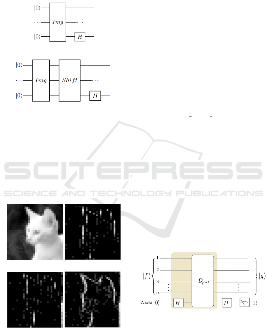
Here's a circuit drawing to extract all the edge
information from the image (Cavalieri, 2020).
Figure 1: Circuit to get the differences (c
0
− c
1
), (c
2
− c
3
).
Figure 2: Circuit to get the differences (c
1
– c
2
), (c
3
– c
4
).
From the results of the matrix equation (4), horizontal
edge detection can be obtained between pairs of even
number pixels: 0 & 1, 2 & 3, etc. and horizontal edge
detection between pairs of odd number pixels: 1 & 2,
2 & 3, etc. So to obtain the value of the amplitude
permutation in the quantum register by converting the
amplitude vector (c
0
, c
1
, c
2
,…., c
N-1
)
T
into (c
1
, c
2
,
c
3
,…., c
N-1
)
T
. After that, it is transformed with an H
gate and the quantum register measurements are
carried out on the LSB until it becomes
|
1
⟩
. In
general, the following examples of image processing
can be seen (Cavalieri, 2020).
(a) (b)
(c) (d)
Figure 3: Example (a) image source, (b) image processing
result from fig. 1, (c) image processing results from fig. 2
and (d) merging fig. 3, fig. 4 and fig. 5.
From research (yao, 2017) it can be varied
with additional qubits to the quantum register so that
it can expand the QHED algorithm in computing even
and odd pixel pairs simultaneously. For example,
from the previous step, initialize
|
𝐼𝑚𝑔
⟩
=
(𝑐
,𝑐
,𝑐
,…,𝑐
)
. Then the H gate is applied to
additional qubits with initialization
|
0
⟩
. In the end it
produces a redundancy (n + 1) qubits in the image
represented by equation (5). Furthermore, the unity of
the amplitude permutation is defined in equation (6)
to change the amplitude into a structure that will
facilitate the calculation of the image gradient value
for the next stage.
|
𝐼𝑚𝑔
⟩
⊗
(|
⟩
|
⟩)
√
=
√
⎣
⎢
⎢
⎢
⎢
⎢
⎢
⎢
⎢
⎢
⎡
𝑐
𝑐
𝑐
𝑐
𝑐
𝑐
⋮
𝑐
𝑐
𝑐
𝑐
⎦
⎥
⎥
⎥
⎥
⎥
⎥
⎥
⎥
⎥
⎤
(5)
𝐷
=
⎣
⎢
⎢
⎢
⎢
⎢
⎡
0100…00
0010…00
0001…00
0000…00
⋮⋮⋮⋮⋱⋮⋮
0000…01
1000…00
⎦
⎥
⎥
⎥
⎥
⎥
⎤
(6)
Equation (6) is also known as the decrement gate (D)
which can efficiently decompose the unitary result
into a group of rotational gates, both single and multi-
X controlled in the quantum register (Yao, 2017).
More details can be seen in the following circuit
picture.
Figure 4: the QHED circuit with an auxiliary qubit.
By applying the gate 𝐷
, will transform (c
0
, c
0
, c
1
,
c
1
, c
2
, c
2
, …. , c
N-2,
c
N-2,
c
N-1
, c
N-1
)
T
into (c
0
, c
1
, c
1
, c
2
,
c
2
, …. , c
N-2,
c
N-1
, c
N-1
, c
0
)
T
. Then, by applying the H
iCAST-ES 2022 - International Conference on Applied Science and Technology on Engineering Science
910
gate to the additional qubits, we get a gradient for
even and odd pixel pairs simultaneously.
(
𝐼
⊗ 𝐻
)
.
⎣
⎢
⎢
⎢
⎢
⎢
⎢
⎢
⎢
⎢
⎡
𝑐
𝑐
𝑐
𝑐
𝑐
𝑐
⋮
𝑐
𝑐
𝑐
𝑐
⎦
⎥
⎥
⎥
⎥
⎥
⎥
⎥
⎥
⎥
⎤
→
⎣
⎢
⎢
⎢
⎢
⎢
⎢
⎢
⎢
⎢
⎡
𝑐
+ 𝑐
𝑐
− 𝑐
𝑐
+ 𝑐
𝑐
− 𝑐
𝑐
+ 𝑐
𝑐
− 𝑐
⋮
𝑐
+ 𝑐
𝑐
− 𝑐
𝑐
+ 𝑐
𝑐
− 𝑐
⎦
⎥
⎥
⎥
⎥
⎥
⎥
⎥
⎥
⎥
⎤
(7)
measurement of this condition against additional
qubits in the
|
1
⟩
measurement of this condition
against additional qubits in the c
i
– c
i+1
gradient for all
possible values of the adjacent pair of qubits.
Meanwhile, to get the edge detection value of the
image vertically, you can use the transpose matrix of
the image and then follow all the steps that have been
described previously. For the final stage in producing
the full edge detection method from this process, the
results of processing horizontally and vertically must
be combined.
2 EXPERIMENTAL
PROCEDURES
This chapter focuses on the implementation of all the
steps described in the previous chapter. while the
image dataset tested used a benchmark dataset from
contour detection and image segmentation resources
from the Berkeley Computer Vision Group
(Arbelaez, 2010). The program code is built using
Qiskit and simulated with Qiskit backend state vector
simulator. The hardware used is Dell Inspiron 3881
with 16 GB RAM memory (DDR4 SDRAM),
Intel(R) Core(TM) i7-10700F CPU @ 2.90 GHz (8
Core) and Windows 10 Home Single Language 64 Bit
Operating System.
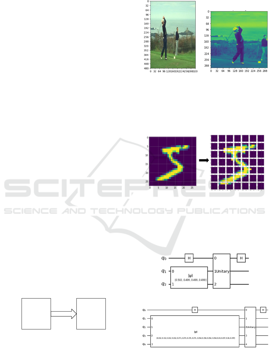
The first step is preprocessing image data that will
be processed into QHED (Pramanik, 2021).
Figure 5: Preprocessing image data.
(a) (b)
Figure 6: Example preprocessing image data : (a) RGB
image with 481 x 321 pixel and (b) B&W image with 321
x 321 pixel.
Then, the number of qubits (N-qubits) and the chunk
size of 2
cp
re selected to divide the n x n pixel images
into 2
cp
x 2
cp
(Anand, 2022).
Figure 7: splitting n x n images into 2
cp
x 2
cp
.
the number of qubits here is used to design the
quantum circuit of fig.7. So, suppose the pair (2, 1)
N-qubits = 2 and cp = 1, then the appropriate chunk
size is 2
cp
= 2
1
= 2. and so on where N-qubits are
increased by 2 and cp is increased by 1 to (4,2), ( 6,3),
(8, 4) and so on.
Figure 8: Example the QHED circuit with 2 qubit.
Figure 9: Example the QHED circuit with 4 qubit.
Source
Image
(RGB)
width x height
Image Data
(B&W)
n x n
transformation
Experimental Demonstration of the Effect of the Number of Qubits Against CPU Processing Time on Quantum Hadamard Edge Detection
(QHED)
911
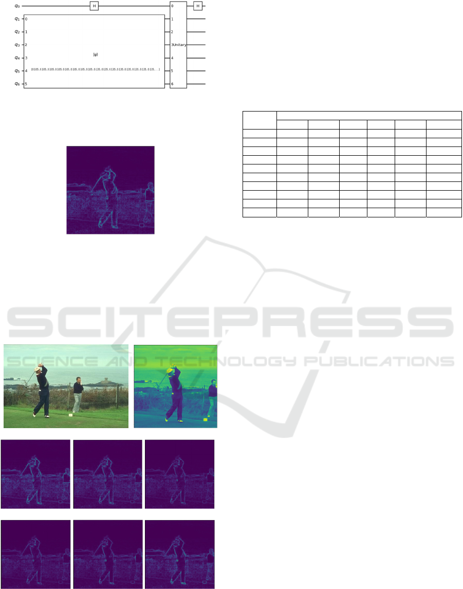
Figure 10: Example the QHED circuit with 6 qubit.
The final result of the QHED process can be seen in
the following image.
Figure 11: Sample Results from the QHED.
3 EXPERIMENTAL RESULTS
A summary of test results with several image datasets
used can be seen in the appendix while examples of
test results can be seen in fig. 14 below.
(a) (b)
(c) (d) (e)
(f) (g) (h)
Figure 12: (a) source image (481 x 321), (b) image data
(321 x 321), (c) QHED with 2 qubit, (d) QHED with 4
qubit, (e) QHED with 6 qubit, (f) QHED with 8 qubit, (g)
QHED with 10 qubit, (h) QHED with 12 qubit.
From the test of some of these images, it can be seen
that the highest number of segmentation in the image
edge detection process is using 2 qubits.
Next, the test results of the effect of the number of
qubits on CPU processing time can be seen in table 1.
below.
Table 1: The number of qubits against CPU processing time
(in seconds).
Image
number
Number of qubits
2468 10 12
1 695.68 90.16 29.25 45.76 304.59 3617.65
2 662.92 89.67 29.42 45.77 299.38 3617.10
3 795.43 103.92 33.14 49.78 361.90 5198.49
4 787.02 104.95 33.64 49.53 362.96 5183.79
5 784.99 104.34 33.44 51.20 362.05 5217.86
6 813.74 104.12 33.53 51.83 363.50 5221.86
7 756.80 99.51 32.50 48.90 362.74 5192.29
8 795.24 102.92 33.07 49.44 360.61 5221.80
9 766.54 103.11 33.26 49.31 358.62 5188.92
10 791.13 103.09 33.35 51.27 361.27 5216.15
it can be seen from table 1. Overall the fastest
processing time in QHED is using 6 qubits and the
longest is using 12 qubits. if we look at it as a whole,
it turns out that the more the number of qubits used,
the longer the processing time, but here it is found that
something is different, namely the processing time
using 2 qubits where the processing time is relatively
longer compared to the number of qubits of 4, 6, 8 and
10. This can happen because at the QHED stage there
is a process of dividing one image into several smaller
image groups by splitting the images into 2
cp
x 2
cp
as
described in fig. 10. This study also conducted tests
with 14 qubits but there was a failure in memory
allocation (RAM) in this case 16 GB of RAM was
unable to process all stages and data in QHED.
4 CONCLUSIONS
The results of this experiment show that theoretically
QHED can perform the edge detection process in
images, but from the tests carried out it was proven
that the number of qubits greatly affects the CPU
processing time where the fastest processing time lies
in the use of the number of qubits as much as 6 qubits,
not in the the least amount is 2 qubit. While the best
edge detection results using 2 qubits. Then testing
with a number of qubits greater than 12 qubits with
16 GB of memory (RAM) cannot be done in other
words if we want to do processing with a larger
number of qubits than all the stages and parameters in
this study must require a larger memory (RAM)
capacity as well.
iCAST-ES 2022 - International Conference on Applied Science and Technology on Engineering Science
912

ACKNOWLEDGEMENTS
This research was funded by Politeknik Negeri
Bengkalis in an internal research grant (PNBP 2022)
on an applied research scheme.
REFERENCES
Anand, A., Lyu, M., Baweja, P. S., & Patil, V. (2022).
Quantum Image Processing. arXiv preprint
arXiv:2203.01831.
Arbelaez, P., Maire, M., Fowlkes, C., & Malik, J. (2010).
Contour detection and hierarchical image
segmentation. IEEE transactions on pattern analysis
and machine intelligence, 33(5), 898-916.
Cavalieri, G., & Maio, D. (2020). A quantum edge
detection algorithm. arXiv preprint arXiv:2012.11036.
Geng, A., Moghiseh, A., Redenbach, C., & Schladitz, K.
(2022). A hybrid quantum image edge detector for the
NISQ era. arXiv preprint arXiv:2203.12072.
Pramanik, S., Chandra, M. G., Sridhar, C. V., Kulkarni, A.,
Sahoo, P., DV, V. C., ... & Nambiar, M. (2021). A
quantum-classical hybrid method for image
classification and segmentation. arXiv preprint
arXiv:2109.14431.
Ruan, Y., Xue, X., & Shen, Y. (2021). Quantum image
processing: opportunities and challenges. Mathematical
Problems in Engineering, 2021.
Wang, Z., Xu, M., & Zhang, Y. (2021). Review of quantum
image processing. Archives of Computational Methods
in Engineering, 1-25.
Yan, F., Iliyasu, A. M., & Venegas-Andraca, S. E. (2016).
A survey of quantum image representations. Quantum
Information Processing, 15(1), 1-35.
Yao, X. W., Wang, H., Liao, Z., Chen, M. C., Pan, J., Li, J.,
... & Suter, D. (2017). Quantum image processing and
its application to edge detection: theory and
experiment. Physical Review X, 7(3), 031041.
Yuan, S., Venegas-Andraca, S. E., Wang, Y., Luo, Y., &
Mao, X. (2019). Quantum image edge detection
algorithm. International Journal of Theoretical Physics,
58(9), 2823-2833.
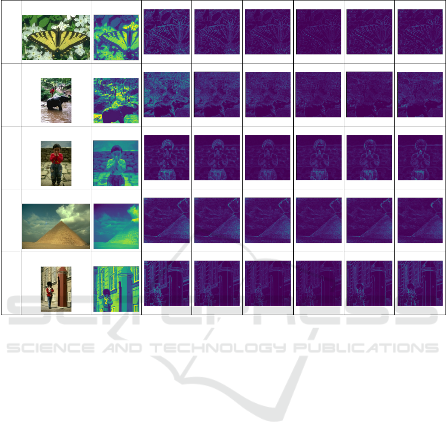
APPENDIX
No.
Source images
(w x h)
Images data
(n x n)
Number of qubits
2 4 6 8 10 12
1
(321 x 481)
(321 x 321)
2
(481 x 321)
(321 x 321)
3
(321 x 481)
(321 x 321)
4
(481 x 321)
(321 x 321)
5
(481 x 321)
(321 x 321)
Experimental Demonstration of the Effect of the Number of Qubits Against CPU Processing Time on Quantum Hadamard Edge Detection
(QHED)
913
6
(481 x 321)
(321 x 321)
7
(321 x 481)
(321 x 321)
8
(321 x 481)
(321 x 321)
9
(481 x 321)
(321 x 321)
10
(321 x 481)
(321 x 321)
iCAST-ES 2022 - International Conference on Applied Science and Technology on Engineering Science
914
