
Preliminary Development of Concrete 3D Printing Machine
Controller Based on Mach3 Control Board
Herman Budi Harja
a
, Heri Setiawan
b
, Dede Buchori Muslim
c
, Akil Priyamanggala
d
and Rahma Dwi Kurniawan
e
Department of Manufacture Engineering, Politeknik Manufaktur Bandung, Kanayakan, Bandung, Indonesia
rahmadk2019.tmu@gmail.com
Keywords: PC Based, Concrete 3D Printing, X-Y-Z Axis, Extruder, Controller Configuration.
Abstract: The implementation of 3D printing concept for civil buildings significantly affects construction time, cost,
and design flexibility. This paper proposed the configuration of a concrete 3D printing controller using PC-
based and March 3 6 to control the X-Y-Z axis movement, sense the axis travel limit, and concrete nozzle
feeder. The component configuration of object study 3D printing use five MCDLT35SF as servo motor driver
of the X-Y-Z axis, five Panasonic AC servo motor as X-Y-Z axis actuator, one Nema motor stepper as an
extruder, eight limit switches as axis travel limit. The parameter configuration value has been determined
referring to the properties of actuator and sensor installed. Those parameters setting is slaving axis, port
address, kernel speed, and In-out pin setting. Slaving axis method is used to accommodate the axis that needs
two actuator motors, such as on X-axis and Y-axis machine. The proposed controller configuration was
verified experimentally, all actuators and travel limits could respond as a command.
1 INTRODUCTION
Additive Manufacturing (AM) can be the focus of
industry and government investment or can even be
used to make objects or components in everyday life
(Gibson, 2015).
One of the additive manufacturing technologies is
the 3D Printing Machine for Buildings. 3D printing is
a manufacturing activity that produces 3-dimensional
objects or products from a design program. The
printer will read the program design file and print
layer by layer made of geopolymer mortar until the
entire object is reached. The advantage of this
machine is that it can make buildings automatically
and quickly (Nithesh, 2018). The working principle
of 3D Printing for buildings is to print one layer to the
next according to the height, length, and height of the
3D object design according to the program specified.
Computer-based control is a development of
analog control in the past. Computer-based control
a
https://orcid.org/0000-0001-9746-2647
b
https://orcid.org/0000-0001-8767-1429
c
https://orcid.org/0000-0001-9872-7248
d
https://orcid.org/0000-0002-3453-0056
e
https://orcid.org/0000-0003-1493-5504
can provide input directly to the driving tool, besides
that this control can also receive input signals from
the correction tool used. One of the computer-based
controls is the Mach3 Novusun 6 Axis. This device
has the advantage of having 6-axis ports, and ease of
setting the parameters, besides that this device is
specifically designed for the use of CNC (Computer
Numeric Control). Its device is supported by Cura as
CAM software in the 3D printing process. Where the
G-code 3D printing that comes out on the Cura
software has been adjusted to the G-Code on this
device. With these advantages, Mach3 Novusun 6
Axis was chosen as the control device for concrete 3D
printing machine.
Several researchers have studied Mach 3
implementation as machine controller. Gonzale
developed CNC milling using March 3 and PLC
S71200 for controlling the three-axis movement of
CNC milling (Meza, 2018). Boral state
implementation of the Mach3 and the Smoothstepper
Harja, H., Setiawan, H., Muslim, D., Priyamanggala, A. and Kurniawan, R.
Preliminary Development of Concrete 3D Printing Machine Controller Based on Mach3 Control Board.
DOI: 10.5220/0011958800003575
In Proceedings of the 5th International Conference on Applied Science and Technology on Engineering Science (iCAST-ES 2022), pages 931-936
ISBN: 978-989-758-619-4; ISSN: 2975-8246
Copyright © 2023 by SCITEPRESS – Science and Technology Publications, Lda. Under CC license (CC BY-NC-ND 4.0)
931
controller is very effective and allows achieving the
high rotational speeds of motors without losing steps
(Boral, 2019). Alvares explained using Mach 3-
Matlab for retrofitting the industrial robot ASEA
IRB2-S6 (Alfares ,2017).
The aim of this research is to configure the
controller for concrete 3D printing machine using
March 3 control board and to ensure the performance
of device control runs properly and appropriately.
Hence, it is necessary to determine the appropriate
parameters.
2 METHOD AND RESULT
Developing the controller configuration for a
concrete 3D printing machine has several stages:
identification of the certain input-output component
of machine, determination of wiring component
system, identification of detail component as pin
number and its function, determination of value for
each parameter set, and verification of the system
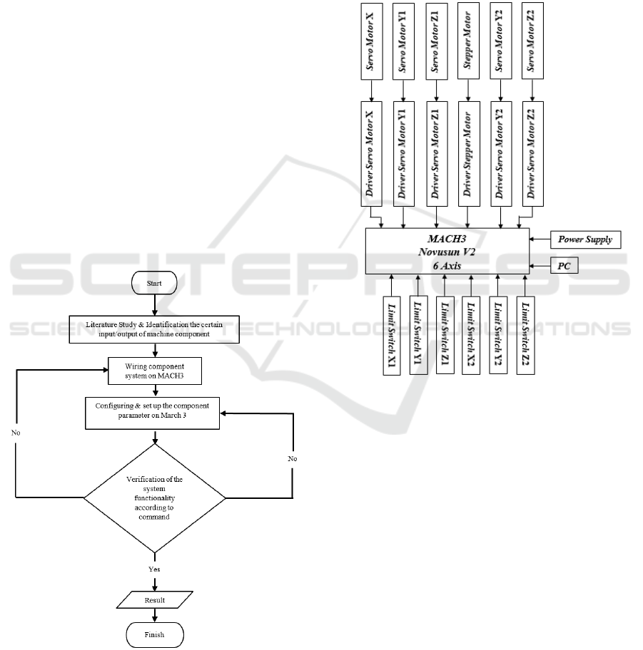
functionality. Figure 1 shows the stages of the
development study to configure and determine the
parameter setting of the concrete 3D printing
machines.
Figure 1: Development study to configure and determine
the parameter setting of concrete 3D printing machine.
The certain input-output component of concrete
3D printing has three axes movement actuator (X-Y-
Z axes), one nozzle actuator as feeder concrete, and
several limit switch sensors and others.
Figure 2 shows the wiring diagram of concrete 3D
printing machine. Mach3 control board is connected
to PC (Personal Computer), power supply, limit
switch of each axis, and servo motor driver.
Determination of the relation between components
system could be seen on wiring diagram.
Figure 2: Wiring diagram of concrete 3D printing machine.
MACH 3 is designed to control machine tools
such as lathes, plasma cutting machines, and 3D
printers (Gorman, 2017). MACH3 mostly works on
PCs with windows operating systems to control the
movement of stepper motors and servo motors by
processing G-code data. Mach3 software display is
seen in Figure 3.
Several parameters on the MARCH 3 breakout
board system should be set up such as unit, port
address, slaving unit, kernel speed, input and output
pin, and motor tuning. Figure 4 shows the setting
stages of MARCH 3 parameters.
iCAST-ES 2022 - International Conference on Applied Science and Technology on Engineering Science
932
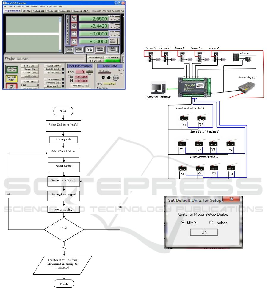
Figure 3: March 3 software display (
ArtSoft
, 2008).
Figure 4: Setup March 3 parameter.
The control system uses Novusun 6 Axis Mach3
BOB as the controller. It is connected to 5
MCDLT35SF servo motor drivers (X, Y, Z, B, and C
axis), 1 TB6600 stepper motor driver (A axis), 5
Panasonic AC Servo Motors 750W (X, Y, Z, B, and
C axis), 1 Nema 34 Stepper Motor (A axis), 8 Limit
Switches, and 24V Power Supply. Figure 5 is
illustrated the March 3 wiring diagram for 3D
printing.
The main menu of Mach 3 has a "config" menu
which has a "Select Native Unit" sub-menu. The
menu is provided to determine the standard unit of
measure to be used. In this feature there are two units,
namely mm and inch (ArtSoft, 2008). The features of
the native unit can be seen in Figure 6.
Figure 5: Wiring diagram March 3.
Figure 6. Native unit setting.
The axis of large machines often requires two
actuator motors installed on each side of axis slider.
It could use the Config>Slave Axis dialog to
configure Mach 3, hence one axis movement (ex. X-
axis) is the main motor and supports another motor
(perhaps the C axis is configured as linear rather than
rotary) (ArtSoft, 2008). The parameter setting is
shown in Figure 7.
The port address on March 3 is set with a value of
the parallel port address of the PC author. If the PC
author has a parallel port address of 0x378, hence the
port address should be set to 0x378 as shown in
Figure 8.
Preliminary Development of Concrete 3D Printing Machine Controller Based on Mach3 Control Board
933
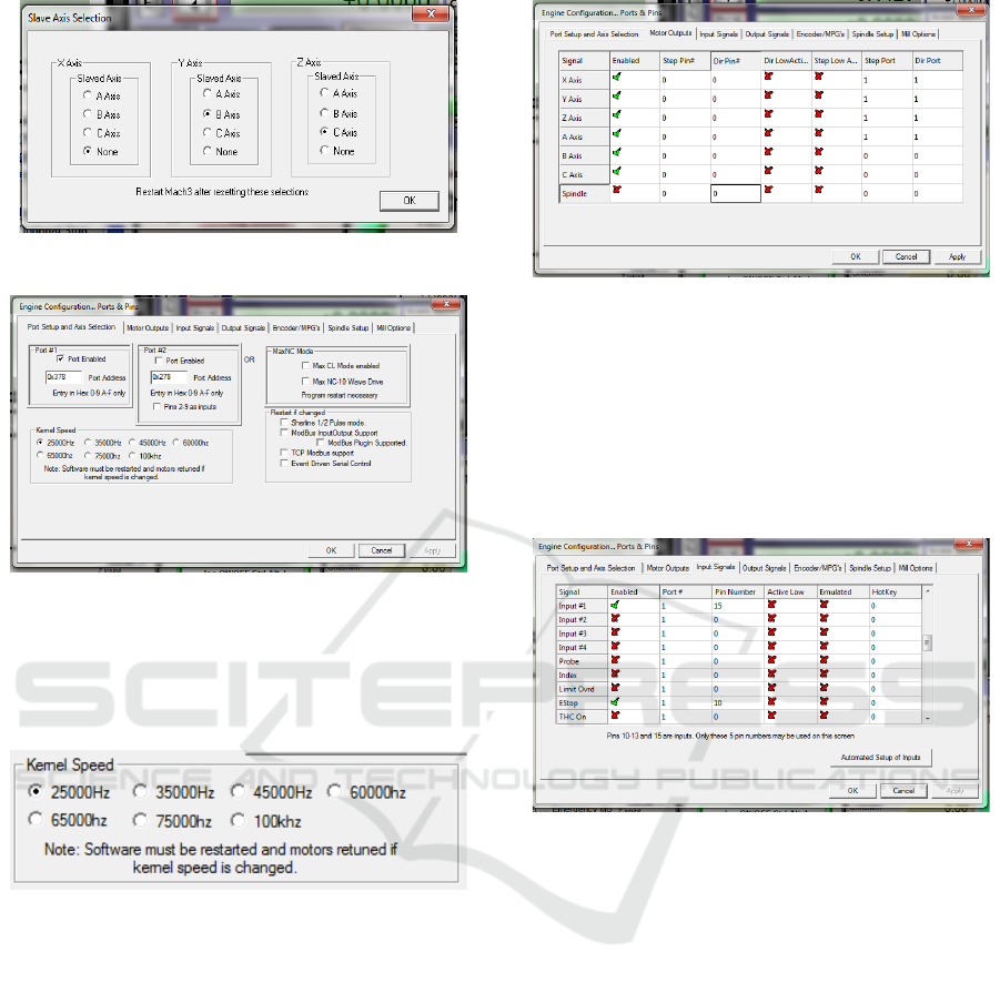
Figure 7: Slaving axis unit setting.
Figure 8: Port address setting.
Kernel speed is the speed parameter of the signal
number that is sent from the computer to the Mach 3
BOB. It is adjusted to the capacity of our computer
processor [3]. This setting can be seen in Figure 9.
Figure 9: Kernel speed setting.
Determine where the motors for your X, Y, and Z
axes are connected, and click in the Enabled column
to get a checkmark to enable these axes. If any axes
are enabled that are not supposed to be, click on the
Enabled column to change the green tick to a red “X”
[3]. The output motor pin settings that the author did
can be seen in Figure 10.
Figure 10: Pin-out motor setting.
The input signal will provide an input signal to the
Mach 3 program. Pin numbering refers to the port
address used. In the author's trial, the author uses a
limit switch as a sensor for the limit of the axis
movement and the Push Button Emergency Stop as
an emergency switch. The input signal settings that
the author made can be seen in Figure 11.
Figure 11: Input signal axis setting.
2.1 Calculation of the Motor Tuning
Motor tuning aims to set the step value of each axis.
The motor tuning value is calculated based on several
parameters such as output driver pulse, tooth pitch of
timing belt, and number of teeth on the slider drive
gear. Several formulations for the calculation of servo
motor tuning are shown in formulas (1), (2), (3), and
(4).
Shaft revs/unit = 1/ (tp x Ns) (1
)
M
otor revs/unit = shaft revs/unit x (Ns/Nm) (2
)
Pulse/motor revs = PPR x 4 (3)
Step/unit = Pulse/motor revs x Motor
revs/unit
(4)
If the output driver is 2500 pulse per rotation [p/r],
tooth pitch of timing belt is 0.2inchi or 5.08mm, teeth
iCAST-ES 2022 - International Conference on Applied Science and Technology on Engineering Science
934

number on motor is 20. Using formulation (1) until
(4), the value of motor tuning is shown.
• Shaft revs/ unit = 1/ (5.08 x 90) = 0.00218
rev/mm.
• Motor revs/unit = 0.00218 x (90/20) = 0.00981
revs/mm
• Pulse/ motor revs = 2500 x 4 = 10,000 pulse/revs
• Step/ unit = 10,000 x 0.00981 = 98.1 steps/mm
Motor tuning of the stepper motor is calculated by
formulas (5), (6), (7), and (8).
Screw revs/unit = 1/
p
itch (1)
Motor revs/unit = screw revs/uni
t
(2)
Motor step/revs = 360°/step moto
r
(3)
Step/unit = Motor step/revs x Motor
revs/unit
(4)
Several values of motor stepper are known, such
as step motor is 1.8° and screw pitch is 45mm. Hence
the motor stepper value can be calculated.
• Screw revs/unit = 1/45 =0.022 revs/mm.
• Motor revs/unit = 0.022 revs/mm.
• Motor step/revs = 360°/1.8° = 200 steps/revs
• Step/ unit = 200 x 0.022 = 4.44 step/mm.
Figure 12 shows the servo motor setting for X-
axis. The motor tuning value is set at 98.1 step/mm.
The motor stepper tuning value of the A-axis with
4.44 step/mm is shown in figure 13.
Figure 12: Servo motor setting.
Figure 13: The setting of motor stepper.
2.2 Verified the Functionality of
System
Experimentally verified was conducted for (i)Testing
of axis movement direction and (ii) Rotation speed of
axis motor. Each servo motor axis such as X-axis, Y-
axis, and slave Y-axis (or B-axis), Z-axis and slave Z-
axis (or C-axis), and A-axis were tested in clockwise
and counterclockwise direction. Table 1. Show tested
data of movement direction motor axis. The
experiment results show that each axis servo motor
has been rotated refer to G-code command.
Table 1: Tested data of movement direction.
Command Axis Drive Moto
r
Direction
X-50
X
Axis motor X CCW
X50 Axis motor X CW
Y-50
Y
Axis motor Y CCW
Axis motor B CW
Y+50
Axis motor Y CW
Axis motor B CCW
Z-50
Z
Axis motor Z CCW
Axis motor C CW
Z+50
Axis motor Z CW
Axis motor C CCW
A-50
A
Axis motor A CCW
A+50 Axis motor A CW
Testing of rotation speed of axis servo motor was the
way to verify the velocity parameter of axis
movement without mechanical components of axis
machine. Three velocity parameters were tested, 62.3
mm/second, 187.24 mm/second, and 249.69
mm/second. The specification of servo motor has 98
steps per unit and 2500 pulse per rev, hence rotation
speed could be calculated. Experimentally tested
rotation speed was measured by tachometer.
Preliminary Development of Concrete 3D Printing Machine Controller Based on Mach3 Control Board
935

3 CONCLUSIONS
The controller of concrete 3D printing has been
developed using Mach 3 control board with PC-based
type and supported by Cura as CAM software in the
3D printing process. The parameter setup has been
properly determined; hence each X-Y-Z axis machine
actuator, extruder actuator, and each limit sensor are
well connected with controller. The proposed
controller configuration was verified experimentally,
all actuators and travel limits could respond as
commands.
REFERENCES
Alvares, A. J., Toquica, J. S., Lima, E. J, and Bomfim, M.
H. S. (2017). Retrofitting of ASEA IRB2-S6 industrial
robot using numeric control technologies based on
Linux CNC and Mach3-Matlab. IEEE International
Conference on Robotics and Biomimetrics ROBIO.
Macau.
Arifin, Z. (2016). Penggunaan ARTSOFT MACH3 Untuk
Gerak Pada Simulator CNC. Tesis. Department of
Mechanical Engineering. Sepuluh Nopember Institute
of Technology. Surabaya.
ArtSoft. (2008). Mach 3 CNC Controller Software
Installation and Configuration. 3
rd
ed. ArtSoft USA.
Boral, P. [2019]. The design of the CNC milling machine.
MATEC Web of Conferences 254.
Deck, K. (2020). Determine RPM stepper Motor.
https://sciencing.com/determine-rpm-stepper-motors-
10033323.com. Access on 21 July 2022.
Gibson, I., Rosen, D. and Stucker, B. (2015). Additive
Manufacturing Technologies. Springer New York
Heidelberg Dordrecht. London.
Gorman, W., Hasting, C., and Pfaff, D. (2017). Building a
3D Printer: Motors and Controls. Worcester
Polytechnic Institute.
Harizal, I. (2017). Rancang Bangun Sistem Kontrol Mesin
CNC Milling 3 Axis Menggunakan Close Loop System.
Thesis. Department of Mechanical Engineering. Riau
University. Riau.
Meza, G., Carpio, C. D., Vinces, N., and Klusmann, M.
(2018). Control of three-axis CNC machine using PLC
S7 1200 with the Mach 3 software adapted to a modus
TCP/IP network. IEEE XXV International Conference
on Electronics, Electrical Engineering and Computing
INTERCON. Peru.
Nithesh, N. (2008). Development of concrete 3D printing.
Thesis. Aalto University.
iCAST-ES 2022 - International Conference on Applied Science and Technology on Engineering Science
936
