
Analysis of Damping Characteristics of Distributed Synchronous
Condenser with Different Configuration
Chengxiang Huo
1
, Rui Song
2
, Dengfeng Li
3
, Pengcheng Guo
4
, Yuchen Feng
4
and Ancheng Xue
4,*
1
China Electric Power Research Institute Co., Ltd., China
2
Electric Power Research Institute State Grid Qinghai Electric Power Co.,Ltd.Qinghai Province, China
3
Electric Power Research Institute State Grid Chongqing Electric Power Co., Ltd.Chongqing Province, China
4
State Key Laboratory of Alternate Electrical Power System with Renewable Energy Source, North China Electric Power
University, Changping, Beijing, BJ 10, China
Keywords: Distributed Synchronous Condenser, Excitation, PSS, Eigenvalue Analysis, Damping.
Abstract: The distributed synchronous condenser (DSC) can not only improve the voltage stability of the power system
interconnected with wind power and photovoltaic, but also improve the damping characteristics of the system.
However, the DSC has many types, and the damping of different types of DSC are unknown. This paper
analyzes the damping characteristics of DSCs with different configurations, based on the eigenvalue analysis
method. Specifically, firstly, the mathematical models of DSCs with different types of rotors, excitation
systems and power system stabilizers (PSS) are established. Secondly, combined with the single machine
infinite bus (SMIB) system, the damping characteristics of different types of DSCs are analyzed and
compared. Finally, combined with the four-machine two-area (4M2A) system, the damping characteristics of
different types of DSC are analyzed and compared. The above work can provide reference for the
configuration of distributed synchronous condenser in power system.
1 INTRODUCTION
In order to deal with the depletion of fossil energy,
climate change and environmental crisis, different
countries vigorously develop the new energy. The
installed capacity of new energy sources such as wind
power and photovoltaic power plant growth rapidly
(Zhenya, 2016; Xioxin et al., 2014; Wanxing et al.,
2019). However, the new energy sources such as wind
power and photovoltaic, are usually concentrated at the
remote sending end of the power grid, which is far
away from the load center and short of reactive power
support. Furthermore, to the new energy sources, its
voltage regulation ability, high and low voltage ride-
through ability and inertia of the superimposed new
energy units, are far less than those of the conventional
units, resulting in the instability problem of sending
end power system interconnected with the new energy,
even induce large-scale cascading off grid accidents
(Jingzhe et al., 2015; Song and Frade, 2016; Gu et al.,
2018), and the distortion of stability of the sending end
system, in the case of fault occurs(Jingzhe et al., 2015).
To solve the above problems, the installation of the
synchronous condenser is a more effective method.
*
Corresponding author
The synchronous condenser is a synchronous motor
under special operating conditions, which can be
regarded as a synchronous generator without active
load or a synchronous motor without mechanical load.
The synchronous condenser can continuously adjust
the reactive power by adjusting the excitation voltage
to achieve reactive power support, while providing
inertia and improving stability (Zhenya et al., 2015;
Yating et al., 2017; Jin et al., 2018; Zhengpai et al.,
2015).
There are two kinds of synchronous condensers:
centralized synchronous condenser (CSC) and
distributed synchronous condenser (DSC). For the
wind or the photovoltaic power stations, the DSCs are
currently recommended (Suo et al., 2019; Li et al.,
2021; Xi et al., 2022; Bingchen, 2021).
Currently, the research about synchronous
condensers, mainly focused on its voltage support level
location and configuration scheme. For example. Ref.
(Suo et al., 2019) compared the configuration schemes
for centralized and decentralized access of
synchronous condensers to different voltage levels,
The results show that the distributed synchronous
condenser can solve the transient overvoltage problem
Huo, C., Song, R., Li, D., Guo, P., Feng, Y. and Xue, A.
Analysis of Damping Characteristics of Distributed Synchronous Condenser with Different Configuration.
DOI: 10.5220/0012004300003612
In Proceedings of the 3rd International Symposium on Automation, Information and Computing (ISAIC 2022), pages 627-632
ISBN: 978-989-758-622-4; ISSN: 2975-9463
Copyright
c
2023 by SCITEPRESS – Science and Technology Publications, Lda. Under CC license (CC BY-NC-ND 4.0)
627

of the sending end system. Ref. (Li et al., 2021) shows
that the scheme of connecting the distributed
condenser to the 35kV bus of the new energy station
has better reactive power compensation effect. Ref.
(Wang et al., 2022) shows that the installation of the
condenser can effectively increase the generalized
short circuit ratio of the system, and puts forward the
location scheme of the reasonable configuration of the
condenser. Ref. (Li et al., 2017) proposed a distributed
/ centralized hybrid optimal configuration scheme
based on the short circuit ratio of multiple new energy
stations, which can improve the voltage support
strength of the grid after the access of new energy with
the minimum total capacity. In addition, ref.
(Yingkunet al., 2022) systematically analyzes the
influence of various electrical parameters on the
transient and sub-transient characteristics of the
condenser, extracts the key technical parameters and
measures for the dynamic performance optimization of
the condenser, and gives suggestions for the specific
optimization design scheme of the condenser.
On the other hand, the synchronous condenser has
inertia, and will also impact the damping
characteristics of the power system. However, there is
few research in this area. In particular, the DSC has
different types, what are the damping characteristics of
different types of DSC, and which type of DSC has the
best effect to improve the damping, has not been
reported.
In reorganization the above, this paper analyze the
influence of DSC with different types of rotors,
excitation systems and PSS on the damping
characteristic with the SMIB and 4M2A systems
through eigenvalue analysis, and explore the guidance
for the equipment selection of DSC.
The remainders of the paper are organized as
follows. Section 1 introduces different types of DSC
models, including different types of rotors, excitation
systems and PSS. Section 2 analyzes and compares the
damping characteristics of different types of DSC in a
SMIB system. Section 3 analyzes and compares the
damping characteristics of different types of DSC in
the 4M2A system. Finally, Section 4 gives the
conclusion.
2 MODELS FOR DISTRIBUTED
CONDENSER
2.1 DSC Body Model
According to the difference of the distributed
synchronous condenser body, excitation system and
PSS, the distributed synchronous condenser has
different Configuration.
The body of the DSC can be divided into two
categories: hidden pole and salient pole. Hidden pole
condenser is usually horizontal, its advantages are
small size, easy installation of infrastructure, small
starting system capacity, relatively simple rotor
structure, easy maintenance; and its disadvantage is
that the phase depth is poor, generally about half of the
rated capacity. Salient pole condenser is usually
vertical, the volume of salient pole condenser increases
exponentially with the increase of pole pair, so its
infrastructure cost is high, the starting system capacity
is large; rotor structure is relatively complex, body
maintenance is slightly larger, but its advantage is that
the leading phase capacity is equivalent to the rated
capacity, and the cooling system is relatively simple.
The mathematical model of hidden pole machine
and salient pole machine can be written as:
0
"
"'"'"
0
"
"'"'"
0
'
'
'''"
0
'"
'
'
'' '"
0
'"
(1)
1
((1))
()
()
()
()
e
j
q
dqqddd
d
qddqqq
q
dd
dfq qq
dd
qq
d
qd dd
qq
d
dt
d
TD
dt T
dE
TEExxi
dt
dE
TEExxi
dt
dE
xx
TEE EE
dt x x
xx
dE
TE EE
dt x x
δ
ωω
ω
ω
=⋅−
=⋅−− −
=−− −
=−+−
−
=−− −
−
−
=− − −
−
(1)
where 𝛿 is the power angle of the synchronous
condenser; 𝜔 is the rotating speed of the synchronous
condenser; 𝜔
0
is the synchronous speed of the
synchronous condenser; 𝑇
is the inertia time constant,
D
is the damping coefficient, 𝑇
is the electromagnetic
torque of the synchronous condenser. 𝐸
'
(𝐸
'
) and 𝐸
''
(𝐸
''
) are respectively q(d)-axis transient electromotive
force and sub-transient electromotive force,
respectively. 𝐸
is excitation electromotive force,
q
x
(𝑥
), 𝑥
'
(𝑥
'
) and 𝑥
''
(𝑥
''
) are q(d)-axis synchronous
reactance, transient reactance and sub-transient
reactance respectively. 𝑇
0
'
(𝑇
0
'
) and 𝑇
0
''
(𝑇
0
''
) are the
q(d)-axis open-circuit transient time constant and sub-
transient time constant, respectively. 𝑖
and 𝑖
q
i
are
the d-axis and q-axis components of the stator current,
respectively.
ISAIC 2022 - International Symposium on Automation, Information and Computing
628
For the hidden pole machine, there is
dq
x
x=
,
dq
x
x
′′ ′′
=
; while for the salient pole machines, there is
dq
x
x≠
,
dq
x
x
′′ ′′
≠
.
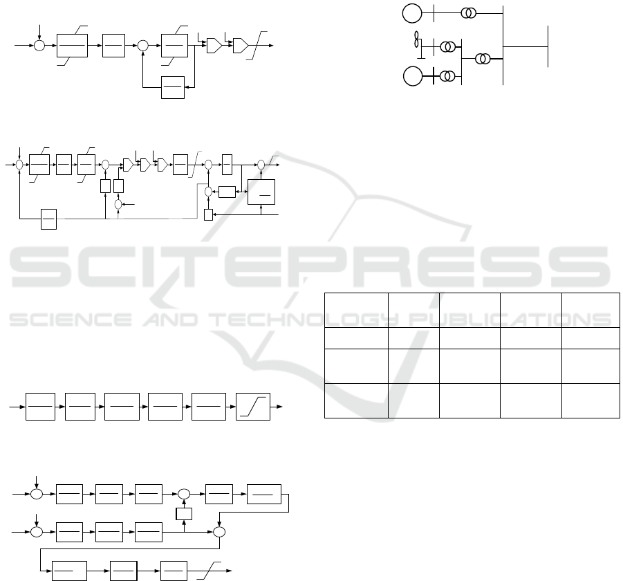
2.2 Excitation Model
There are two types of excitation models commonly
used in DSCs, i.e., the FV type and FM type. The FV
type belongs to the self-shunt static excitation system,
as shown in Figure 1; the FM type is an AC exciter
system, as shown in Figure2.
+
1
2
(1 )
v
K
sT
K
sT
+
+
3
4
1
1
s
T
s
T
+
+
1
A
A
K
s
T+
1
F
F
sK
s
T+
F
D
E
ERR
V
S
V
1AMAX
V
AMAX
V
AMIN
V
1AMIN
V
-
+
+
L
V
H
V
L
V
H
V
TRMAX CFD
VV K I−
TRMIN CFD
VV K I−
Figure 1: Model block diagram of FV excitation system
+
1
2
(1 )
v
KsT
KsT
+
+
3
4
1
1
s
T
s
T
+
+
1
A
A
K
s
T+
1
F
F
sK
s
T+
FD
E
ERR
V
S
V
1AMAX
V
AMAX
V
AMIN
V
1AMIN
V
-
+
+
HV
H
V
H
K
1L
K
1L
V
2L
V
1
LV
2
LV
5
1
B
K
s
T
+
1
E
s
T
D
K
EE
SK+
()
EX N
FfI=
CFD
N
E
KI
I
V
=
∏
-
-
+
1LR
V
+
-
+
+
RMAX
V
RMIN
V
E
V
FDMAX
E
FD
I
Figure 2: Model block diagram of FM excitation system.
2.3 PSS Model
There are two types of PSS models commonly used in
distributed synchronous condensers, i.e., the SS type
and SI type. The SS type is PSS1A type, as shown in
Figure 3. The SI type belongs to PSS2B type, as shown
in Fig.4.
1
1
1
1
Q
Q
s
T
s
T
′
+
+
2
2
1
1
Q
Q
s
T
s
T
′
+
+
3
3
1
1
Q
Q
s
T
s
T
′
+
+
SMAX
V
SMIN
V
S
V
1
Q
Q
s
T
s
T+
1
QS
QS
K
s
T+
ω
Δ
Figure 3: Model block diagram of SS-type PSS.
+
+
1
1
rw
s
T+
5
6
1
s
T
s
T+
7
7
1
s
T
s
T+
1
r
rp
K
s
T+
1
1
w
w
T
s
T+
2
2
1
w
w
sT
s
T+
9
10
1
1
s
T
s
T
+
+
4
12
1
1 sT
+
1
2
1
1
p
sT
K
sT
+
⋅
+
13
14
1
1
s
T
s
T
+
+
3
4
1
1
s
T
s
T
+
+
s
K
+
+
-
-
ω
0
ω
G
P
0G
P
+
-
SMAX
V
SMIN
V
S
V
Figure 4: Model block diagram of SI PSS.
3 DAMPING PERFORMANCE IN
THE SMIB SYSTEM
This section analyzes and compares the damping
characteristics of different types of DSC in a SMIB
system. Specifically, a DSC is added to a single
machine infinite bus system, as shown in Figure 5. The
eigenvalue method is used to compare the
corresponding damping ratio.
0U∠
SC
=
g
U
θ
∠
SG
P
MSG
Figure 5: Single machine infinite bus system structure
3.1 Damping with Different Rotors
The eigenvalue and damping ratio of the system of
following three cases: the system without a condenser,
the system with a condenser and the rotor with hidden
poles and salient poles, can be obtained, respectively,
as shown in table 1.
Table 1: Eigenvalue and damping ratio of SMIB system with
different types of rotors for condenser.
Rotor type
Real
part
Imaginary
part
Frequency
Damping
ratio
- -0.188 5.874 0.935 0.032
Hidden
pole
-0.202 5.794 0.922 0.035
Salient
pole
-0.229 5.786 0.921 0.039
Table 1 shows that the rotor with salient pole type
has better effect on improving the system damping
than the rotor with hidden pole type.
3.2 Damping with Different Excitation
The frequency and damping ratio of the system with
FV-type and FM-type excitations can be obtained,
respectively, as shown in table 2.
Analysis of Damping Characteristics of Distributed Synchronous Condenser with Different Configuration
629
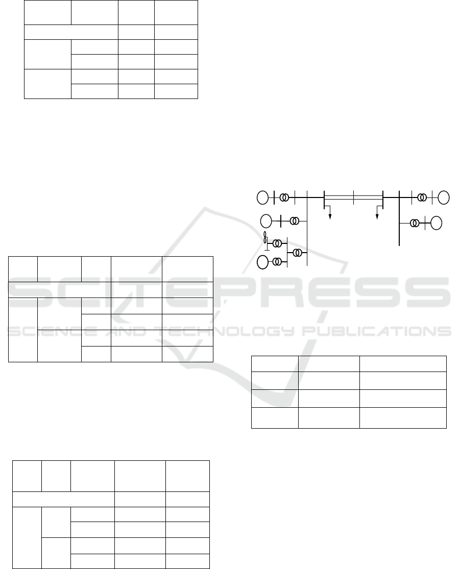
Table 2: Frequency and damping ratio of SMIB system with
different excitation systems for condenser.
Rotor type
Type of
excitation
Freque
ncy
Damping
ratio
- 0.935 0.032
Hidden
pole
FV 0.925 0.033
FM 0.922 0.035
Salient
pole
FV 0.922 0.038
FM 0.921 0.039
Table 2 shows that the FM type excitation system
has a better effect on the system damping in both the
hidden pole condenser and the salient pole condenser.
3.3 Damping with Different PSS
Considering the SS-type and SI-type for PSS, the
frequency and damping ratios of the system can be
obtained, as shown in Table 3 and Table 4.
Table 3: Frequency and damping ratio of SMIB with
different types of PSS for hidden pole condenser.
Rotor
type
Excitatio
n
PSS Frequency
Damping
ratio
- 0.935 0.032
Hidd
en
pole
FV
SS 0.920 0.038
SI 0.923 0.037
FM
SS 0.931 0.041
SI 0.923 0.039
Table 3 shows that in the hidden pole condenser,
whether the excitation system is FV type or FM type,
the SS type PSS has a better effect on the system
damping.
Table 4: Frequency and damping ratio of SMIB system with
different types of PSS for salient pole condenser.
Rotor
Excit
ation
PSS Frequency
Damping
ratio
- 0.935 0.032
Salie
nt
pole
FV
SS 0.921 0.042
SI 0.918 0.041
FM
SS 0.927 0.044
SI 0.922 0.042
Table 4 shows that in the salient pole condenser,
whether the excitation system is FV type or FM type,
the SS type PSS has a better effect on the system
damping.
4 RESULTS IN THE 4M2A
In this section, the damping characteristics of different
types of DSC in a modified 4M2A system, are
analyzed and compared.
Specifically, the DSCs is installed to the modified
4M2A system with wind power interconnection as
shown in Figure 6. The eigenvalues and corresponding
damping ratios of the system are calculated by
eigenvalue method, and the damping variations of the
system with different types of rotors, excitation
systems and PSS are compared.
1 5 6 7 8 9 10 11 3
2
4
G
1
G
2
G
3
G
4
12
SC
=
1
L
2
L
P
MSG
Figure 6: Four-machine two-area system structure diagram.
The oscillation modes of the 4M2A system
without SDCs are shown in Table 5.
Table 5: Oscillation modes of a 4M2A system without a
condenser.
Frequency Damping ratio Correlative unit
1.502 0.075
G1,G2
1.613 0.075
G3,G4
1.052 0.013
G1,G2,G3,G4
Furthermore, after adding the DSC, the damping
ratio of the inter-area oscillation changed, and the
damping ratio of the local oscillation almost
unchanged. Therefore, the following analysis only
focuses on the inter-area oscillation mode between
regions.
4.1 Damping with Different Rotors
For the case with the DSC, considering the rotor
adopting the hidden pole and the salient pole
respectively, the frequency and damping of the system
inter-area oscillation can be obtained as shown in
Table 6.
ISAIC 2022 - International Symposium on Automation, Information and Computing
630

Table 6: Eigenvalues and damping ratios of 4M2A system
with different types of rotors for condenser.
Rotor type Frequency Damping ratio
- 1.052 0.013
Hidden pole 1.052 0.015
Salient pole 1.051 0.017
Table 6 shows that the rotor with salient pole type
has better effect on improving the system damping
than the rotor with hidden pole type.
4.2 Damping with Different Excitation
The frequency and damping ratios of the inter-area
oscillation, considering the FV and FM type
excitations, with used for the hidden-pole and salient-
pole tuners, can be obtained, as shown in Table 7.
Table 7: Frequency and damping ratio of 4M2A system with
different types of excitation systems for condenser.
Rotor type
Type of
excitation
Frequenc
y
Damping
ratio
- 1.052 0.013
Hidden pole
FV 1.055 0.015
FM 1.052 0.015
Salient pole
FV 1.054 0.017
FM 1.051 0.017
Table 7 shows the influence of different types of
excitation systems on system damping is not very
obvious in either the hidden pole condenser or the
salient pole condenser.
4.3 Damping Characteristics with
Different Types of PSS
The frequency and damping ratios of the system inter-
area oscillation can be obtained, as shown in Table 8
and Table 9, considering the SS-type and SI-type PSS
for the hidden polar and salient polar condensers,
respectively.
Table 8: Damping ratio of 4M2A system with different types
of PSS for hidden polar condenser.
Rotor
type
Type of
excitation
Type of
PSS
Freque
ncy
Damping ratio
- 1.052 0.013
Hidd
en
pole
FV
SS 1.055 0.017
SI 1.056 0.016
FM
SS 1.054 0.017
SI 1.054 0.016
Table 8 shows that in the hidden pole synchronous
condenser, no matter the excitation system is FV type
or FM type, SS type PSS has better effect on the system
damping.
Table 9: Damping ratio of 4M2A system with different types
of PSS for salient pole condenser.
Rotor
type
Type of
excitation
Type
of PSS
Frequency
Damping
ratio
- 1.052 0.013
Salie
nt
pole
FV
SS 1.054 0.019
SI 1.054 0.017
FM
SS 1.056 0.019
SI 1.052 0.018
Table 9 shows that in the salient pole synchronous
condenser, whether the excitation system is FV type or
FM type, SS type PSS has a better effect on the system
damping.
In summary, in the four-machine two-area system,
the distributed condenser adopts the salient pole type
rotor, and the SS PSS have the best effect on the system
damping improvement.
5 CONCLUSION
In this paper, through the eigenvalue analysis method,
combined with the SMIB and 4M2A systems, the
damping characteristic of the system are analyzed
when the distributed synchronous condenser(DSC)
adopts different types of rotors, excitation systems and
PSS. The results are as follows.
a) The DSC with salient pole type rotor has better
performance on improving the system damping than
that with hidden pole type rotor.
Analysis of Damping Characteristics of Distributed Synchronous Condenser with Different Configuration
631

b)The FM excitation system has a better
performance on the system damping.
c) In the SMIB and 4M2A system, the SS type for
PSS has better performance on improving the damping.
Thus, from the viewpoint of damping
characteristics, it is better to adopt salient pole system,
FM type excitation system and SS type PSS.
This paper only analyzes the configuration of
distributed condenser types from the viewpoint of
damping characteristics. In the actual configuration,
the voltage and reactive power characteristics, cost
also need to be considered.
ACKNOWLEDGMENTS
This work is supported by project of “Research of
adaptive optimization of distributed synchronous
condensers and its applications in oscillation
suppression in the power interconnected with high-
proportion renewable energy” by the State Grid
Corporation of China.
REFERENCES
Liu Zhenya., 2016.Research of Global Clean Energy
Resource and Power Grid Interconnection. Proceedings
of the CSEE, 36(19):5103-5110.
Zhou Xiaoxin, Lu Zongxiang, Liu Yingmei, et
al.,2014.Development models and key technologies of
future grid in China. Proceedings of the CSEE,
34(29):4999-5008.
Sheng Wanxing, Wu Ming, Ji Yu, et al.,2019. Key
techniques and engineering practice of distributed
renewable generation clusters integration. Proceedings
of the CSEE, 39(8):2175-2186.
Tu Jingzhe, Zhang Jian, Liu Mingsong, et al.,2015 Study on
wind turbine generators tripping caused by HVDC
contingencies of wind-thermal-bundled HVDC
transmission systems. Power System
Technology,39(12):3333-3338.
Song Yipeng, Frade Blaabjerg.,2016. Overview of DFIG-
based wind power system resonances under weak
networks. IEEE Trans-actions on Power
Electronics,32(6):4370.
H. Gu,R. Yan and T.K. Saha.,2018 Minimum Synchronous
Inertia Requirement of Renewable Power Systems.
IEEE Transactions on Power Systems,33(2):1533-1543.
Tu Jingzhe, Zhang Jian, Wang Jianming, et al.,2015.
Mechanism analysis on the sending-side instability
caused by the receiving-side contingencies of large-
scale HVDC asynchronous interconnected power
systems. Proceedings of the CSEE ,35(21):5492-5499.
Liu Zhenya, Zhang Qiping, Wang Yating, et al.,2015.
Research on reactive compensation strategies for
improving stability level of sending-end of 750 kV grid
in Northwest China. Proceedings of the CSEE,
35(5):1015-1022.
Wang Yating, Zhang Yichi, Zhou Qinyong, Li Zhiqiang, et
al.,2017. Study on Application on New Generation
Large Capacity Synchronous Condenser on Power Grid.
Power System Technology, 41(01):22-28.
JIN Yiding, YU Zhao, LI Mingiie, et al.,2018 Comparison
of new generation synchronous condenser and power
electronic reactive power compensation devices in
application in UHVDC/AC grid. Power System
Technology,42(7):2095.
Cui Zhengpai, Wang Haojing, Ma Suoming, et al.,2015.
Operation situation analysis and improvement measure
study for dynamic reactive compensation equipment
applied in large-scale wind power systems. Power
System Technology ,39(7):1873-1878.
SUO Zhiwen, LIU Jianqin, JIANG Weiyong, et al.,2019.
Research on synchronous condenser configuration of
large-scale renewable energy DC transmission system.
Electric Power Automation Equipment,39(9):124-129.
LI Zhiqiang, HE Fengjun, GUO Qiang, et al.,2021.
Comparative study on dynamic reactive power
compensation scheme in the concentrated delivery area
of new energy in southern Qinghai. Modern Electric
Power,38(1):87-93.
Xi Gongwei, Zhao Bing, Zheng Shuaifei, et al.,2022.
Transmission Capacity and Improvement Measures of
New Energy Base via UHVAC Transmission System.
Electric Power Construction, 43 (07): 131-138
Liu Bingchen.,2021. Research on dynamic reactive power
compensation scheme of high proportion new energy
transmission system. North China Electric Power
University (Beijing).
WANG Kang, LI Ziheng, YANG Chaoran, et al.,2022.
Siting method of synchronous condenser for small-
signal stability improvement of large-scale renewable
energy base. Automation of Electric Power Systems
,46(4):66-74.
Li Zhiqiang, Jiang Weiyong, Wang Yanbin, et al.,2017. Key
technical parameters and optimal design of new types of
large capacity synchronous condenser. Large Electric
Machine and Hydraulic Turbine, 15-22.
Zhou Yingkun, Sun Huadong, Xu Shiyun, et
al.,2022.Optimal Configuration Method of Adjusting
Camera for Improving Power Grid Voltage Support
Strength. Power System Technology:1-10.
ISAIC 2022 - International Symposium on Automation, Information and Computing
632
