
Drill String Vibration Monitoring as an Element of Automatic Control of
Drilling
Vladimir Morkun
1 a
, Natalia Morkun
1 b
, Vitalii Tron
2 c
, Alona Haponenko
3 d
,
Iryna Haponenko
3 e
and Evhen Bobrov
3 f
1
Faculty of Engineering Sciences, Bayreuth University, Universit
¨
atsstraße, 30, Bayreuth, 95447, Germany
2
Department of Automation, Computer Science and Technology, Kryvyi Rih National University,
11 Vitalii Matusevych Str., Kryvyi Rih, 50027, Ukraine
3
Research Department, Kryvyi Rih National University,
11 Vitalii Matusevych Str., Kryvyi Rih, 50027, Ukraine
Keywords:
Drilling, Vibration, Monitoring, Automatization, Ore, Mining.
Abstract:
The research is aimed at monitoring drill string vibrations as an element of automatic control of the drilling
process. To reduce negative impacts of vibrations occurring in the drill string at deep drilling of hard rocks, a
mathematical model is proposed to consider parameters of the drilling process and predict the penetration rate.
The following parameters are used as input variables when studying drilling data: weight-on-bit, rotations per
minute, torque, mechanical specific energy, longitudinal, transverse and torsional vibrations. In this study,
the rate of penetration is used as a resulting variable. Considering these parameters, a mathematical model of
the drilling process is formed on the basis of adaptive neural-fuzzy inference structures. The accuracy of this
model is 95.56 %.
1 INTRODUCTION
Deep drilling of hard rocks causes strong vibrations in
the drill string associated with a reduced rate of pene-
tration (ROP) and early failure of equipment (Cobern,
2003; Morkun et al., 2015c). The only available
method of limiting vibrations during drilling is to
change the rotary speed or weight-on-bit (WOB). Yet,
these changes often reduce drilling efficiency.
There are a number of vibration sources in a
drilling rig that can potentially reduce the mechani-
cal rate of penetration and cause vibrations damag-
ing sensors and clamps. These include, in particular,
shock vibrations from bit cones and blades (Morkun
et al., 2015c; Golik et al., 2015). There are sev-
eral cones on the bit which make the string vibrate
when moving. Vibration frequency is a multiple of
a
https://orcid.org/0000-0003-1506-9759
b
https://orcid.org/0000-0002-1261-1170
c
https://orcid.org/0000-0002-6149-5794
d
https://orcid.org/0000-0003-1128-5163
e
https://orcid.org/0000-0002-0339-4581
f
https://orcid.org/0000-0002-9275-3768
the speed of the bit blades.
Besides, in drilling there is a direct precession –
lateral vibration – caused by imbalance in the drill
string (Cobern, 2003; Morkun et al., 2015b). The
imbalance can occur due to peculiarities of machin-
ing drill collars or due to their curvature, these caus-
ing lateral vibrations along the drill string. The re-
verse precession is caused by friction between the
drill string and the borehole. If there is a sufficient
contact effort and rotary speed, couplings begin to ro-
tate around the borehole counterclockwise with the
friequency that depends on the external diameter of
the couplings and that of the borehole. This creates
an imbalance effort on the drill string. Excitation is a
multiple of the motor speed multiplied by the number
of rotor blades.
In addition, the stabilizers have blades in contact
with the borehole (Cobern, 2003; Deng et al., 2021).
The resulting excitation is a multiple of the rotary
speed multiplied by the number of blades. Straight
blades cause greater vibration than inclined ones. The
stick-slip phenomenon is another source of vibration
caused by friction between couplings or stabilizers
and the borehole as a result of gravity along the drill
Morkun, V., Morkun, N., Tron, V., Haponenko, A., Haponenko, I. and Bobrov, E.
Drill String Vibration Monitoring as an Element of Automatic Control of Drilling.
DOI: 10.5220/0012009700003561
In Proceedings of the 5th Workshop for Young Scientists in Computer Science and Software Engineering (CSSE@SW 2022), pages 57-62
ISBN: 978-989-758-653-8; ISSN: 2975-9471
Copyright
c
2023 by SCITEPRESS – Science and Technology Publications, Lda. Under CC license (CC BY-NC-ND 4.0)
57
string (Cobern, 2003; Moharrami et al., 2021). This
phenomenon can make the element bit jammed. After
accumulating enough effort to release the drill string,
it resumes its rotation at a high angular speed.
The roller-cone bit is a kind of mechanism that,
when interacting with the borehole bottom, converts
rotation of the drill string or the borehole motor shaft
in longitudinal, torsional, and under certain condi-
tions, transverse vibrations (Novikov and Serikov,
2020; Bogomolov and Serikov, 2018). Strong vibra-
tions during machine operation can cause destruction
of drill collars and derrick elements, damage to bore-
hole motors and equipment, an increase in the bore-
hole diameter, early wear of the bit, reduction of the
mechanical penetration rate. With intensified vibra-
tions and no control of their level, the phenomenon
of resonance can occur, which in most cases results
in severe destruction of elements of drill collars and
the bit (Bogomolov and Serikov, 2018; Morkun et al.,
2015a).
Longitudinal and torsional vibrations are essen-
tially connected with specific design of roller-cone
bits and the principle of their operation (Novikov and
Serikov, 2020; Liu et al., 2021). Vibrations are of a
wavelike nature. They are classified into longitudinal,
transverse and torsional. They occur simultaneously
and depend on wavelike characteristics of the drill
string and devices included in its assembly (calibra-
tors, centrators, dampers, shock absorbers), bit size,
properties of drilled rocks, and drilling mode param-
eters.
The causes of vibrations include a stick-slip nature
of rock destruction, rough borehole bottom (Serikov
and Ginzburg, 2015; Morkun and Tron, 2014), inho-
mogeneity, fracturing and sharp intermittency in hard-
ness of drilled rocks, pressure differences under dif-
ferent support teeth of the bit (Novikov and Serikov,
2020; Serikov et al., 2016), uneven wear of teeth lead-
ing to formation of different contact areas with the
rock; the toothed working surface of the bit, pres-
sure pulsation in the discharge system (Vasiliev et al.,
2015; Morkun et al., 2014) and discrete tool feed.
2 MATERIALS AND METHODS
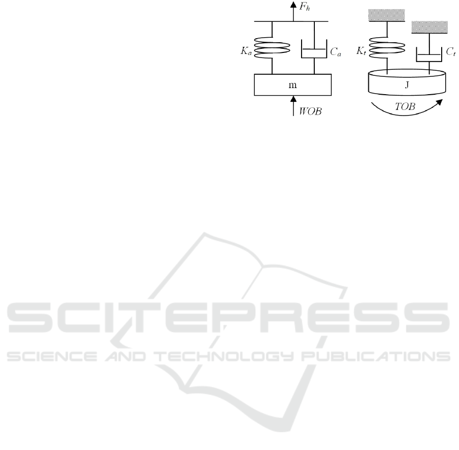
In paper (Sharma et al., 2021) a lumped mass drill rod
model that consists of two degrees of freedom was
suggested. The drill rod is represented by the equiva-
lent mass and rigidity for axial and torsional motions
(figure 1).
Equations of for axial and torsional motions the
drill string are as follows:
Figure 1: Simplified lumped model for axial and torsional
motion: a – axial motion; b – torsional motion (Sharma
et al., 2021).
m ¨x + c
a
˙x + k
a
(x − v
0
∗t) = −W OB (1)
J
¨
θ + c
t
˙
θ + k
t
(θ − Ω ∗t) = −T OB (2)
where m is the effective mass of the drill rod, x is the
axial displacement, J is the effective polar inertia mo-
ment, c
a
s the damping coefficient during the axial
motion, c
t
is the damping coefficient during torsional
motion, k
a
is the axial rigidity, k
t
is the torsional rigid-
ity, v
0
is the initial axial velocity, θ is the angular dis-
placement of the bit and Ω is the surface rotation rate
in radians per second (RPS). Axial and torsional mo-
tion equations (1) and (2) are related due to interaction
forces of the bit.
A method of direct quantitative determination of
various vibration forms with parameters that can be
easily transmitted to the surface was substantiated in
(Cobern, 2003). The system uses four accelerome-
ters and a magnetometer mounted on the drill string.
By using various combinations of accelerometer out-
put signals, it is possible to distinguish a whirl, a
stick slip, a rebound of the bit, and lateral vibrations
from each other. Three accelerometers are mounted
in the cuff at the angle of 120 degrees from each other
and oriented radially to be measured. The fourth ac-
celerometer is installed axially. The magnetometer is
also installed in one of the pockets. The pockets can
also accommodate WOB and TOB (time on bottom)
strain gauges providing a complete toolkit for bore-
hole diagnostics. Installing accelerometers radially
(figure 2) enables direct calculation of various vibra-
tion modes.
Radial accelerometers measure the centrifugal
force, which is directly related to the rotary speed
(Cobern, 2003). As a result, the rotary speed, the
stick-slip and the swirl can be directly calculated.
The magnetometer is used as a backup for measur-
ing the rotary speed. To measure axial vibration, only
a single-axis accelerometer is required. These param-
eters are calculated as follows.
CSSE@SW 2022 - 5th Workshop for Young Scientists in Computer Science Software Engineering
58
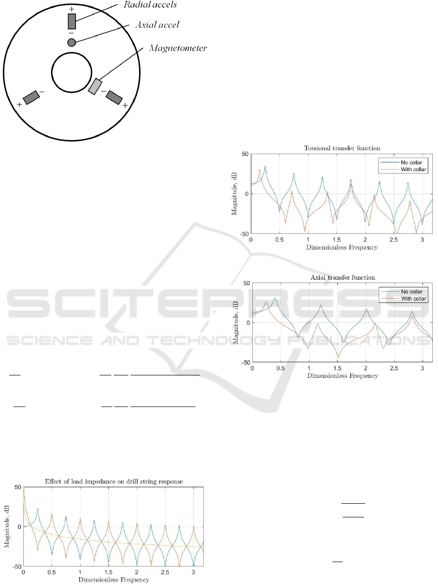
Figure 2: Drill collar sensors.
3 RESULTS AND DISCUSSION
Analysis of frequency characteristics of vibrations
during drill string operation indicates different fre-
quency ranges for individual technical components.
In particular, Cobern (Cobern, 2003) reveals that vi-
brations of components cause vibrations of the fol-
lowing frequency: bit rotation – 1000 Hz, stick-slip
motion of the bit – 10 Hz, direct precession – 10 Hz,
reverse precession – 100 Hz. Also, the vibrations pro-
duced by these sources differ significantly in ampli-
tude.
Transfer functions in a closed form associating de-
formation of the drill string with displacement on the
bit in the dimensionless form are described by the fol-
lowing expressions:
¯
X
b
¯
W
b
( ¯s) = Ψ
a
h
a
( ¯s) = −
Ψ
a
¯s
1
Z
c,a
Z
c,a
+ Z
L,a
tanhΓ
a
Z
L,a
+ Z
c,a
tanhΓ
a
¯
Φ
b
¯
T
b
( ¯s) = Ψ
t
h
t
( ¯s) = −
Ψ
t
¯s
1
Z
c,t
Z
c,t
+ Z
L,t
tanhΓ
t
Z
L,t
+ Z
c,t
tanhΓ
t
Graphical results of modelling the above trans-
fer functions are obtained via software solutions de-
scribed in (Aarsnes and Aamo, 2016) and shown in
figure 3.
Figure 3: Drill collar sensors.
The bottom section of the drill string usually con-
sists of weighted drill collars, which can have a great
impact on dynamics of the drill string due to their ex-
tra inertia. In particular, transition from collars to cou-
plings in the drill string causes reflections in traveling
waves due to a change in the characteristic impedance
of the line.
The length of sections is included in propagation
operators, so they determine basic frequencies of an
individual section. Figure 4 demonstrates the impact
of a 200m drill collar on a 1200m drill string on trans-
fer functions.
(a)
(b)
Figure 4: Transfer function with and without drill collars:
a – torsional, b – axial.
To determine the rotary speed, we calculate the
centripetal acceleration A
c
(t) (Cobern, 2003):
A
c
(t) = (A
1
(t) + A
2
(t) + A
3
(t))
3 (3)
As A
c
(t) = ω
2
(t) − r, where r is the sensor radius, ω
is the angular rotary speed, radian/sec. From here:
ω (t) =
r
A
c
(t)
r
(4)
the instantaneous speed is determined by the expres-
sion:
RPM =
60
2π
· ω (t) (5)
The stick-slip effect is set by the maximum rotary
speed (Cobern, 2003):
ω
ss
= max (ω (t)) (6)
Drill String Vibration Monitoring as an Element of Automatic Control of Drilling
59
The reverse precession is determined by the peak
of the following expression (Cobern, 2003):
A
w
(t) = A
1
(t) + A
2
(t) cos(120 deg)+
+A
3
(t) cos(240 deg)
Lateral vibration has two components. The x-axis
acceleration is equal to:
A
x
(t) =
1
2
A
2
(t) − A
c
(t)
cos(30)
−
A
3
(t) − A
c
(t)
cos(30)
(7)
The y-axis acceleration is determined by the for-
mula:
A
y
(t) =
1
3
(A
1
(t) − A
c
(t)+
−A
2
(t) + A
c
(t)
sin(30)
−
−A
3
(t) + A
c
(t)
sin(30)
)
Thus, the value of lateral vibration is determined
by the vector sum (Cobern, 2003):
A
Lat
(t) =
q
A
x
(t)
2
+ A
y
(t)
2
(8)
Axial vibration can be directly measured with an
axial accelerometer.
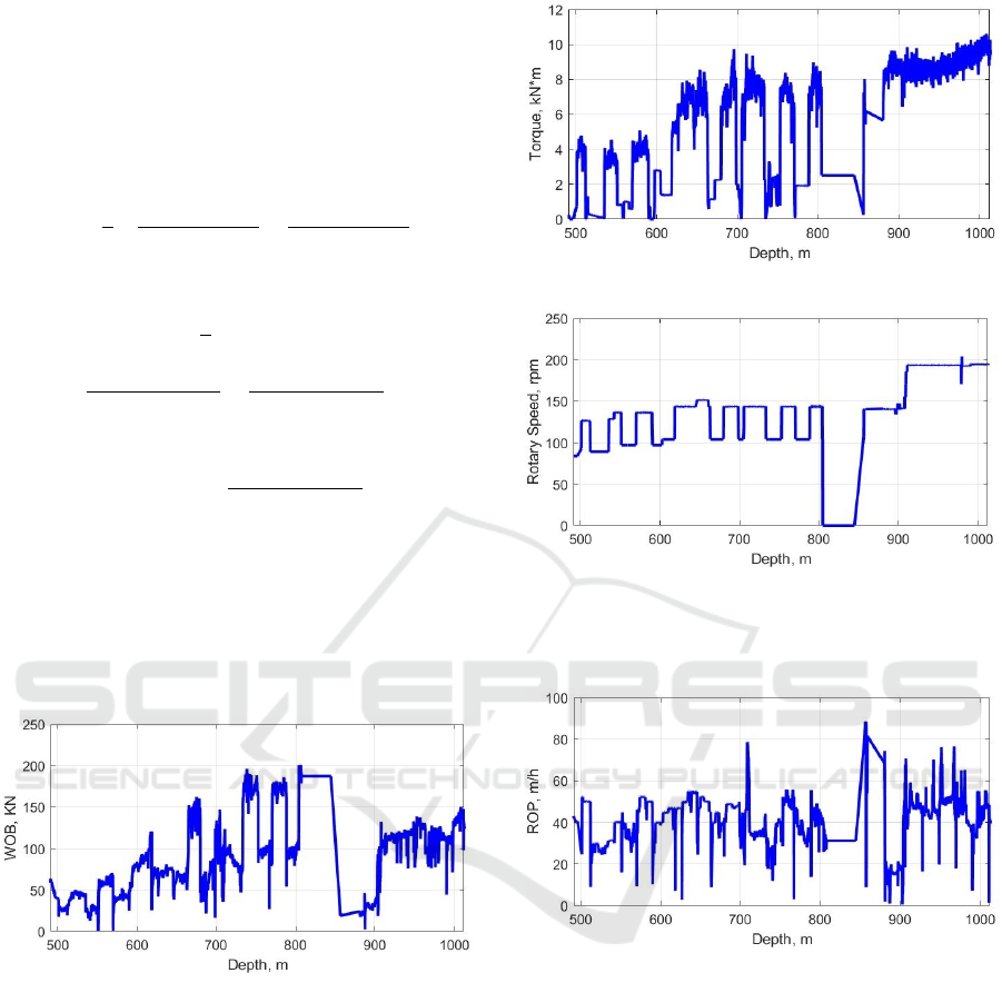
To verify the mathematical model, the data on drill
string operation published in (Tunkiel et al., 2021) is
used. On figure 5 shows the results of measuring the
weight-on-bit depending on the depth of the borehole.
Figure 5: Dependence of the weight-on-bit on the borehole
depth.
The graph of a dependence of the weight-on-bit on
the borehole depth demonstrates characteristic stick-
slip changes in the weight indicator which may be as-
sociated with alternation of various types of drilled
rocks. On figure 6 revealed a dependence of the
torque and the rotary speed on the borehole depth.
These dependences are also characterized by areas
with a stick-slip change in the indicator as in the case
with the WOB indicator.
On figure 7 it is shown the change of the resulting
indicator value (the ROP of the borehole) depending
on the depth.
When studying the data on the drilling process, the
above parameters are used as input variables: WOB,
(a)
(b)
Figure 6: Dependence of the torque and the rotary speed on
the borehole depth: a – torque, b – rotary speed.
Figure 7: Drilling parameters.
RPM, torque, MSE, longitudinal, transverse and tor-
sional vibrations. The resulting variable in this study
is the ROP of the borehole.
Considering the above parameters, a mathemati-
cal model of the drilling process is formed on the ba-
sis of adaptive neural-fuzzy inference structures (AN-
FIS). There are three input terms of membership func-
tions. The type of input membership functions is bell-
shaped. On figure 8 it is shown the results of verifica-
tion of the resulted model.
The verification results of the developed model on
the test sample (figure 8) confirm its applicability to
practical use. The accuracy of this model is 95.56 %.
CSSE@SW 2022 - 5th Workshop for Young Scientists in Computer Science Software Engineering
60
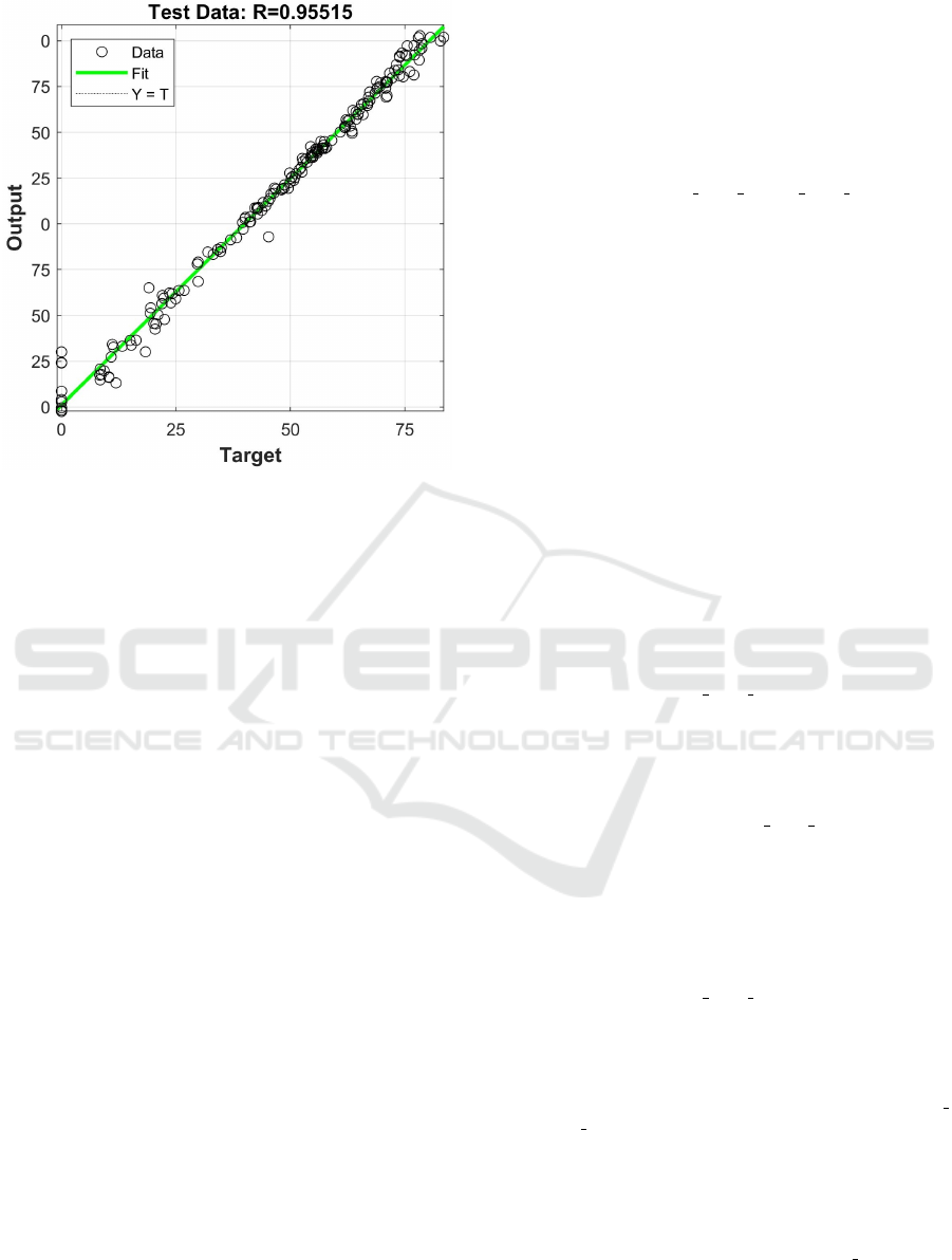
Figure 8: Modelling results.
4 CONCLUSIONS
To reduce negative impacts of vibrations occurring
in the drill string at deep drilling of hard rocks, a
mathematical model is proposed to consider param-
eters of the drilling process and predict the penetra-
tion rate. When studying the data on the drilling pro-
cess, the above parameters are used as input variables:
WOB, RPM, torque, MSE, longitudinal, transverse
and torsional vibrations. The resulting variable is the
ROP of the borehole. Considering the above param-
eters, a mathematical model of the drilling process is
formed on the basis of adaptive neural-fuzzy infer-
ence structures (ANFIS). The accuracy of the given
model makes 95.56 %.
REFERENCES
Aarsnes, U. J. F. and Aamo, O. M. (2016). Linear stabil-
ity analysis of self-excited vibrations in drilling using
an infinite dimensional model. Journal of Sound and
Vibration, 360:239–259. https://doi.org/10.1016/j.jsv.
2015.09.017.
Bogomolov, R. M. and Serikov, D. Y. (2018). Vibration
damper-calibrator. Equipment and Technologies for
Oil and Gas Complex, 3:39–43. https://doi.org/10.
30713/1999-6934-2018-3-39-43.
Cobern, M. E. (2003). Downhole vibration monitoring &
control system. Final report, APS Technology. https:
//doi.org/10.2172/831129.
Deng, P., Zhang, A., Fu, K., and Li, H. (2021). Nonlin-
ear Vibration of a Time-Space Coupled Drill String
System Based on the Surface Morphology of Rock.
Journal of Sound and Vibration, 506:116153. https:
//doi.org/10.1016/j.jsv.2021.116153.
Golik, V., Komashchenko, V., Morkun, V., and
Zaalishvili, V. (2015). Enhancement of
lost ore production efficiency by usage of
canopies. Metallurgical and Mining Indus-
try, 7(4):325–329. https://www.metaljournal.
com.ua/assets/MMI 2014 6/MMI 2015 4/
047-GolikKomashchenkoMorkunZaalishvili.pdf.
Liu, Y., Li, Q., Qi, Z., and Chen, W. (2021). Defect sup-
pression mechanism and experimental study on lon-
gitudinal torsional coupled rotary ultrasonic assisted
drilling of CFRPs. Journal of Manufacturing Pro-
cesses, 70:177–192. https://doi.org/10.1016/j.jmapro.
2021.08.042.
Moharrami, M. J., de Arruda Martins, C., and Shiri, H.
(2021). Nonlinear integrated dynamic analysis of
drill strings under stick-slip vibration. Applied Ocean
Research, 108:102521. https://doi.org/10.1016/j.apor.
2020.102521.
Morkun, V., Morkun, N., and Pikilnyak, A. (2014). Mod-
eling of ultrasonic waves propagation in inhomoge-
neous medium using fibered spaces method (k-space).
Metallurgical and Mining Industry, 6(2):43–48. https:
//www.metaljournal.com.ua/assets/Journal/a8.pdf.
Morkun, V., Morkun, N., and Tron, V. (2015a). Dis-
tributed control of ore beneficiation interrelated
processes under parametric uncertainty. Met-
allurgical and Mining Industry, 7(8):18–21.
https://www.metaljournal.com.ua/assets/Journal/
english-edition/MMI 2015 8/004Morkun.pdf.
Morkun, V., Morkun, N., and Tron, V. (2015b). Iden-
tification of control systems for ore-processing
industry aggregates based on nonparametric kernel
estimators. Metallurgical and Mining Industry,
7(1):14–17. https://www.metaljournal.com.ua/assets/
Journal/english-edition/MMI 2015 1/3%20Morkun,
%20Tron.pdf.
Morkun, V., Morkun, N., and Tron, V. (2015c).
Model synthesis of nonlinear nonstationary dy-
namical systems in concentrating production
using Volterra kernel transformation. Met-
allurgical and Mining Industry, 7(10):6–9.
https://www.metaljournal.com.ua/assets/Journal/
english-edition/MMI 2015 10/001Morkun.pdf.
Morkun, V. and Tron, V. (2014). Automation of
iron ore raw materials beneficiation with the op-
erational recognition of its varieties in process
streams. Metallurgical and Mining Industry, 6(6):4–
7. https://www.metaljournal.com.ua/assets/MMI
2014 6/1-MorkunTron.pdf.
Novikov, A. S. and Serikov, D. Y. (2020). Some features of
the work of drill bits and practical techniques for their
use [Nekotorye osobennosti raboty burovykh dolot i
prakticheskie priemy pri ikh ispolzovanii]. Sphere. Oil
and Gas, 2:44–49. https://xn--80aaigboe2bzaiqsf7i.
xn--p1ai/upload/journal/sphereoilandgas 2020-2.pdf.
Serikov, D. Y. and Ginzburg, E. S. (2015). Increasing the
efficiency of destruction of medium and hard rocks
Drill String Vibration Monitoring as an Element of Automatic Control of Drilling
61

through the use of helical cones [Povyshenie effek-
tivnosti razrusheniia srednikh i tverdykh porod putem
ispolzovaniia kosozubogo vooruzheniia sharoshek].
Equipment and Technologies for Oil and Gas Com-
plex, 4:18–22. https://www.elibrary.ru/item.asp?id=
23868184.
Serikov, D. Y., Panin, N. M., and Ageeva, V. N. (2016).
Improvement of sealing systems for bearing assem-
blies of cone bits [Sovershenstvovanie sistem germeti-
zatcii podshipnikovykh uzlov sharoshechnykh dolot].
Construction of oil and gas wells on land and at
sea, 4:16–19. https://www.elibrary.ru/item.asp?id=
25849083.
Sharma, A., Al Dushaishi, M., and Nygaard, R. (2021).
Fixed Bit Rotary Drilling Failure Criteria Effect
on Drilling Vibration. In U.S. Rock Mechan-
ics/Geomechanics Symposium, volume All Days,
page 116–121. https://onepetro.org/ARMAUSRMS/
proceedings-pdf/ARMA21/All-ARMA21/
ARMA-2021-2083/2480289/arma-2021-2083.pdf.
Tunkiel, A. T., Sui, D., and Wiktorski, T. (2021). Reference
dataset for rate of penetration benchmarking. Journal
of Petroleum Science and Engineering, 196:108069.
https://doi.org/10.1016/j.petrol.2020.108069.
Vasiliev, A. A., Vyshegorodtseva, G. I., and Serikov,
D. Y. (2015). Study of the influence of the flushing
scheme of a roller-cone drill bit on the bottom hole
cleaning [Issledovanie vliianiia skhemy promyvki
sharoshechnogo burovogo dolota na ochistku zaboia
skvazhiny]. Construction of oil and gas wells on land
and at sea, 5:25–28. https://www.elibrary.ru/item.
asp?id=23702308.
CSSE@SW 2022 - 5th Workshop for Young Scientists in Computer Science Software Engineering
62
